Shale shaker screens with aligned wires

Active Publication Date: 2009-03-05
VARCO I P INC
View PDF37 Cites 1 Cited by
  • Summary
  • Abstract
  • Description
  • Claims
  • Application Information

AI Technical Summary

Benefits of technology

[0008]In certain particular aspects, wire alignment in such screen assemblies with multiple screening layers is facilitated by using screen meshes or cloths with a selected number of wires per inch in each layer

Problems solved by technology

In placing one such screen mesh or cloth on top of another, it can happen accidentally that wires of one layer are aligned with wires of another layer; but no effort is made to insure that a large portion, a majority, or substantially all wires of one lay

Method used


Image

  • Shale shaker screens with aligned wires
  • Shale shaker screens with aligned wires
  • Shale shaker screens with aligned wires

Examples


Embodiment Construction

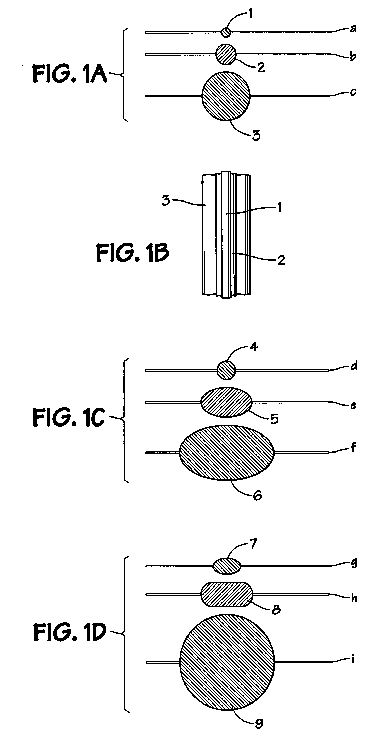
[0087]FIGS. 1A-2D illustrate the definition of “aligned wires.” As shown in FIGS. 1A and 1B, wires 1, 2, 3 in multiple screening material layers a, b, c, respectively are aligned with each other vertically. As viewed from above (FIG. 1B) the wires 1, 2, 3 are in line vertically (at a ninety degree angle to the planes of the screen layers) and, as shown in FIG. 1B, parallel to each other.

[0088]It is within the scope of the present invention to provide a screen assembly with a layer or layers of screen cloth in which wires have a non-round cross-section (whether such a layer is used in a screen or screen assembly without wires aligned or with wires aligned according to the present invention). FIG. 1C shows part of a screen assembly according to the present invention with screen cloth layers d, e. f with aligned wires 4, 5, 6, respectively. Wires 5 and 6 have non-round (oval) cross-sections.

[0089]FIG. 1D shows a portion of a screen according to the present invention with screen cloth l...


PUM


Abstract

A screen for a vibratory separator, the screen including at least two layers of screening material, including a first layer and a second layer, the first layer made of a plurality of intersecting first wires, the second layer made of a plurality of intersecting second wires, the first wires including first shute wires and first warp wires, the second wires including second shute wires and second warp wires, certain of the first warp wires aligned with a second warp wire, and/or certain of the first shute wires aligned with a second shute wire. This abstract is provided to comply with the rules requiring an abstract which will allow a searcher or other reader to quickly ascertain the subject matter of the technical disclosure and is submitted with the understanding that it will not be used to interpret or limit the scope or meaning of the claims, 37 CFR 1.72(b).

Description

BACKGROUND OF THE INVENTION[0001]1. Field of the Invention[0002]The present invention is directed to screens for shale shakers and vibratory separators, and, in certain particular aspects, to screens with aligned wires.[0003]2. Description of Related Art[0004]Vibratory separators are used in a wide variety of industries to separate materials such as liquids from solids or solids from solids. In the oil and gas industries, shale shakers use screens to treat drilling fluid contaminated with undesirable solids. Typically such apparatuses have a basket, deck, or other screen holding or mounting structure mounted in or over a receiving receptacle or tank and vibrating apparatus for vibrating one or more screens. Material to be treated is introduced to the screen(s) either by flowing it directly onto the screen(s) or by flowing it into a container, tank, or “possum belly” from which it then flows to the screen(s).[0005]In a variety of prior art screens, screen mesh or screen cloth as manu...

Claims


Application Information

Patent Timeline
IPC IPC(8): B07B1/46
CPCB07B1/4618E21B21/065B07B1/4672B07B1/4663B07B1/46E21B21/06
Inventor LARSON, THOMAS ROBERTSCHULTE, JR., DAVID LEE
Owner VARCO I P INC
Why Eureka
Try Eureka