Temperature compensating circuit

Active Publication Date: 2005-09-15
RPX CORP
View PDF8 Cites 2 Cited by
  • Summary
  • Abstract
  • Description
  • Claims
  • Application Information

AI Technical Summary

Benefits of technology

[0009] The method and system of the invention provide several advantages. In a preferred embodiment of the invention the temperature slope can be determined as a ratio of resistors and can be arbitrary in magnitude. The

Problems solved by technology

When a base station is located outdoors, the output voltage of a power source drifts with temperature, the variation of which can be very large causing a large variation in amplification.
This kind of solution is very complicated and expensi

Method used


Image

  • Temperature compensating circuit
  • Temperature compensating circuit
  • Temperature compensating circuit

Examples


Example

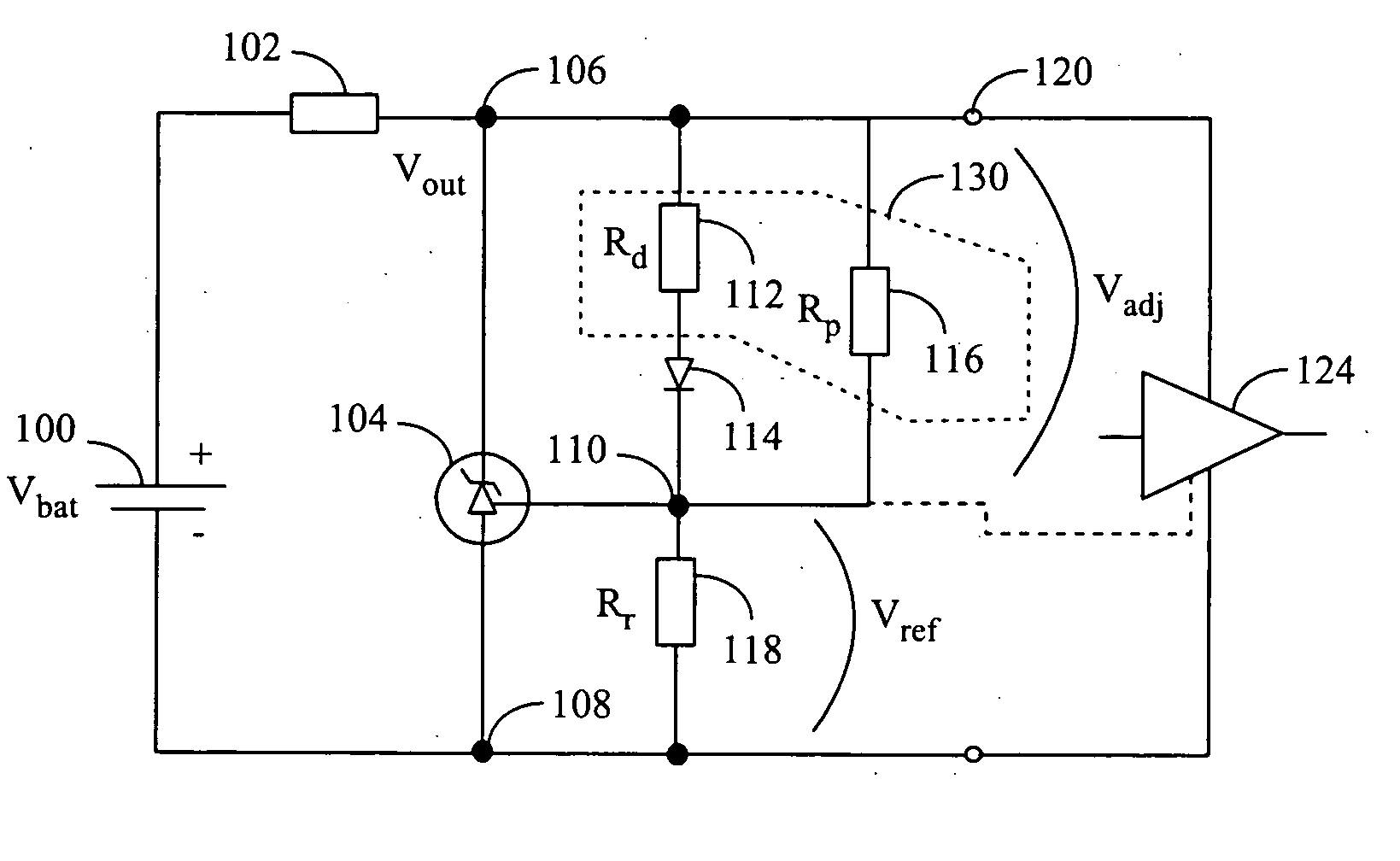
[0016] The present solution is especially suitable for compensating changes in the supply voltage for a power amplifier of a base station operating at radio frequencies without, however, being limited to it.

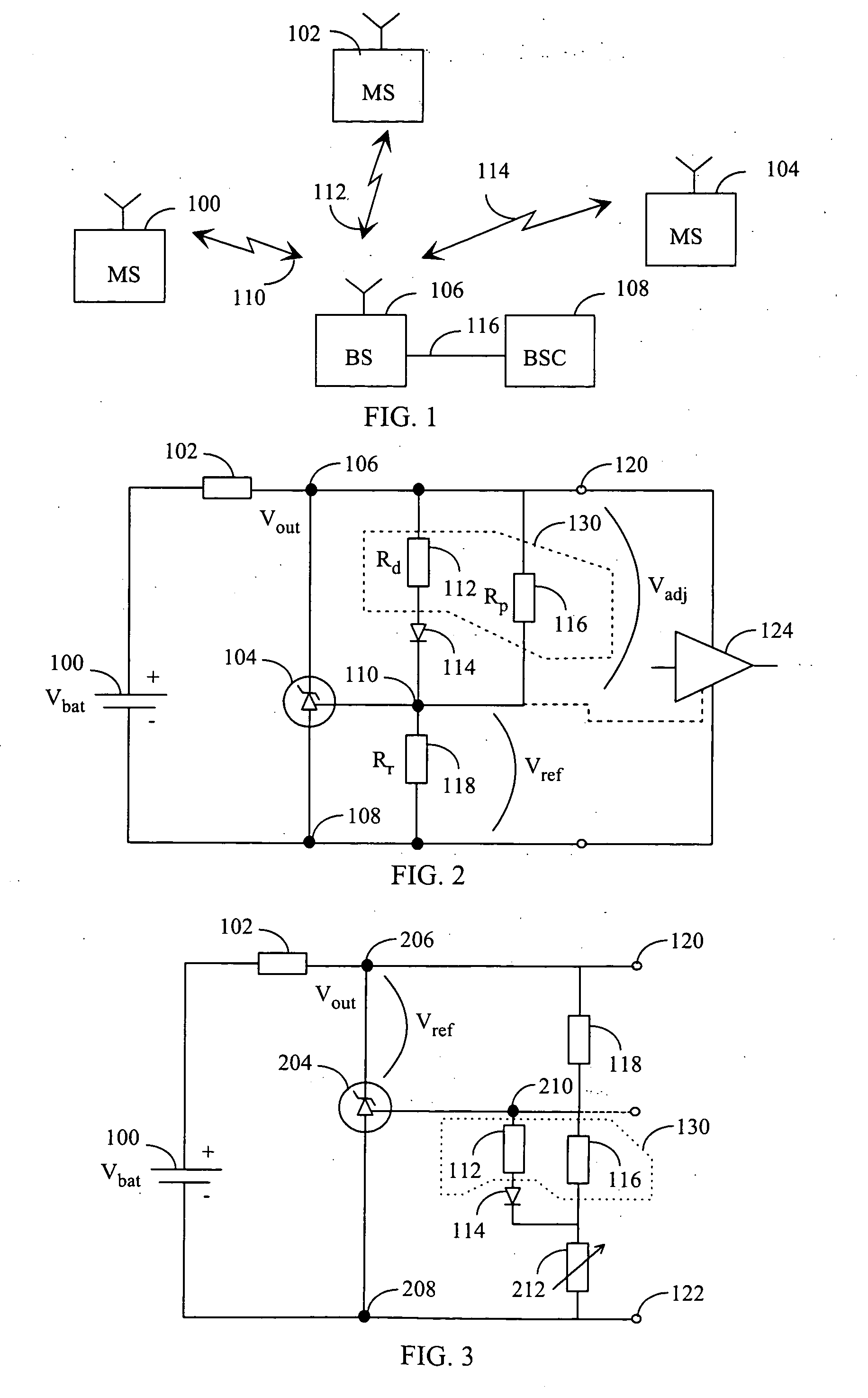
[0017] First the radio system is described by means of FIG. 1. A typical digital radio system comprises subscriber equipment 10 to 14, at least one base station 16, and a base station controller 18, which can also be called a radio network controller. The subscriber equipment 10 to 14 communicates with the base station 16 using signals 20 to 24. The base station 16 can be connected to the base station controller 18 by a digital transmission link 26. The subscriber equipments 10 to 14 may be fixedly installed terminals, user equipment installed in a vehicle or portable mobile terminals. The signals 20 to 24 between the subscriber equipment 10 to 14 and the base station 16 carry digitised information, which is e.g. speech, data information or control information produced by subscr...


PUM


Abstract

The invention relates to a temperature compensating circuit for an amplifier. The circuit comprises a voltage regulator, a component arrangement and a resistor coupling of at least two resistor units. At least part of the output voltage of the temperature compensating circuit is adjustable. The component arrangement includes at least one component with a known temperature dependency of voltage. The resistor coupling forms a slope coefficient as a ratio of values of the resistors in the resistor coupling. The resistor coupling is coupled to the a component arrangement in order to provide the temperature compensating circuit with an output voltage having a temperature dependency which is a function of the slope coefficient and the known temperature dependency of the component arrangement.

Description

FIELD OF THE INVENTION [0001] The invention relates to temperature compensation of a bias voltage of an amplifier. BACKGROUND OF THE INVENTION [0002] Temperature compensation of a bias voltage of an amplifier is important because the amplifier is usually sensitive to changes in voltage of a power source. This is particularly important with the RF power amplifiers, such as LDMOS (Laterally Diffused Metal Oxide Semiconductor) devices, which are used for example in base stations of a radio system. [0003] When a base station is located outdoors, the output voltage of a power source drifts with temperature, the variation of which can be very large causing a large variation in amplification. In prior art the temperature compensation has been performed, for example, by using a sensor and a microcontroller such that the microcontroller with a predetermined control algorithm controls the bias voltage provided by the temperature compensation circuit based on the temperature sensed by the sens...

Claims


Application Information

Patent Timeline
IPC IPC(8): H03F3/04
CPCH03F1/301G05F3/20G05F3/18H03F2200/447
Inventor BARABASH, DARRELL
Owner RPX CORP
Why Eureka
Try Eureka