Microdot printing head

Inactive Publication Date: 2008-09-11
BIO RAD LAB INC
View PDF17 Cites 2 Cited by
  • Summary
  • Abstract
  • Description
  • Claims
  • Application Information

AI Technical Summary

Benefits of technology

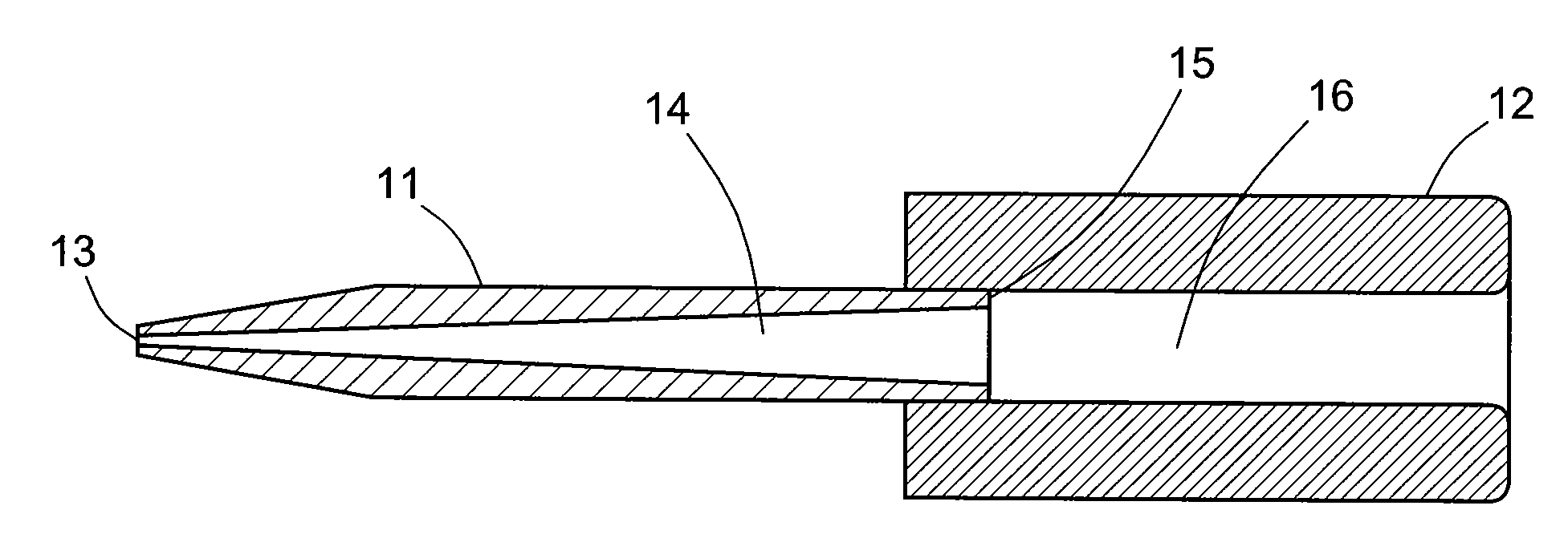
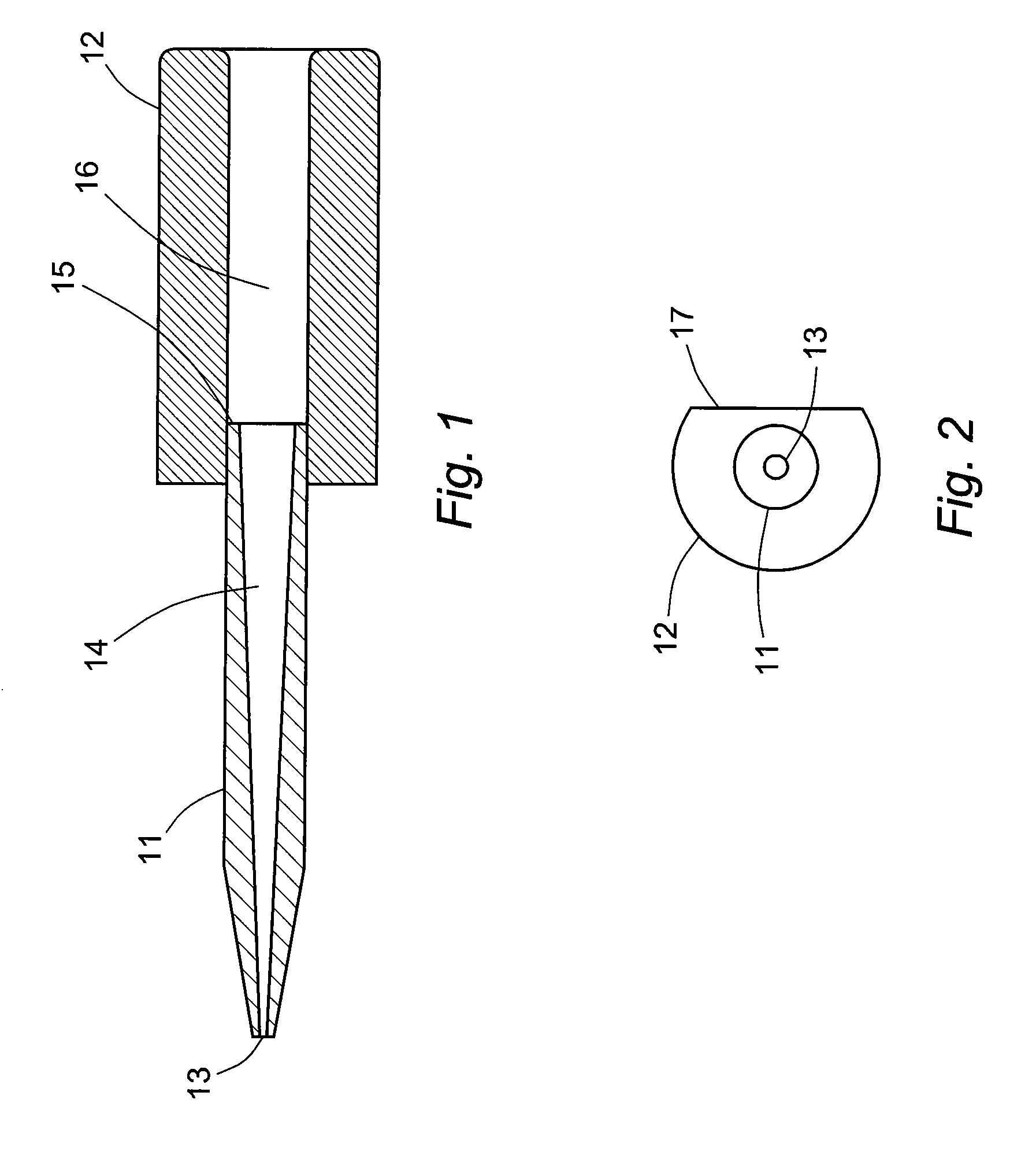
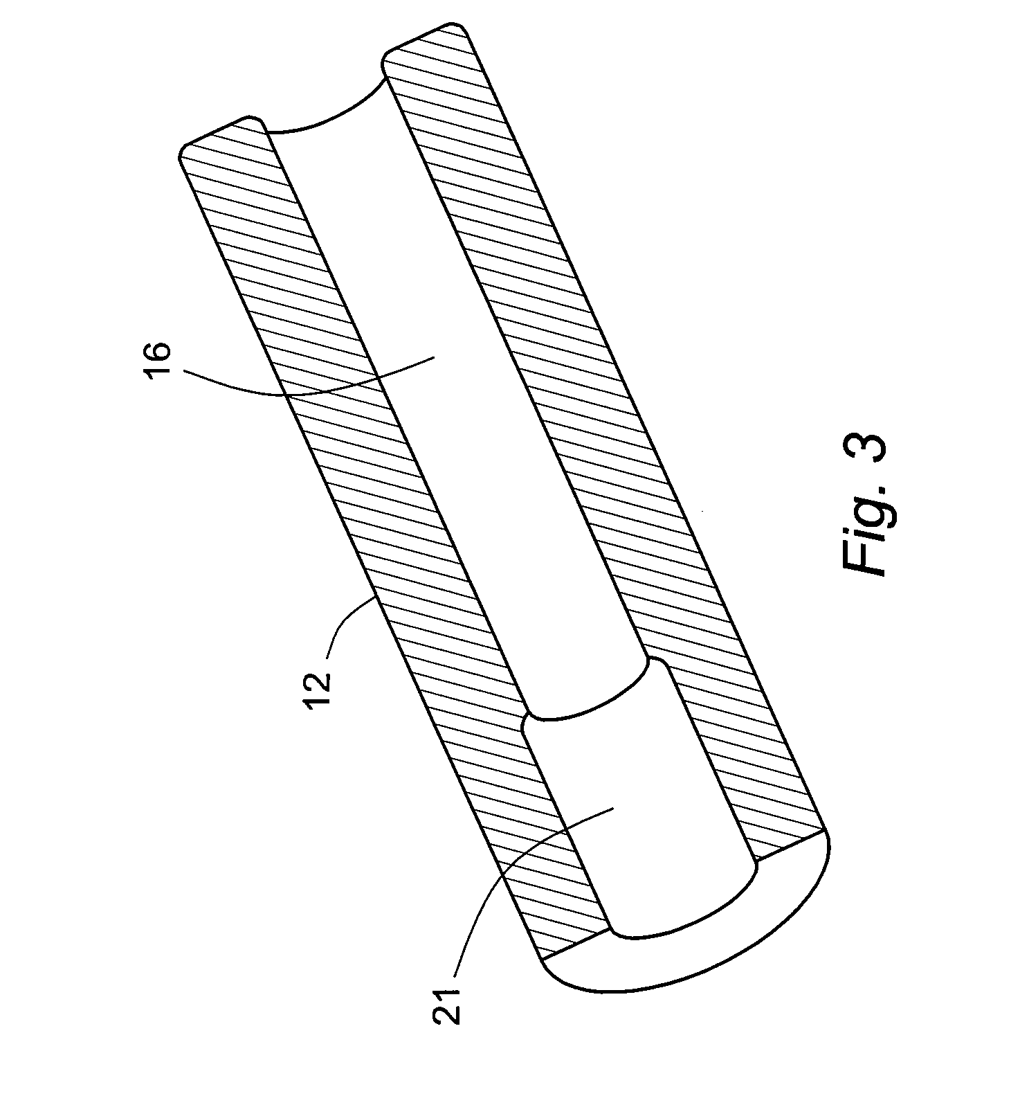
[0006]The present invention resides in the use of hollow pins mounted in bushings that are specially engineered to promote alignment of the pins in the printing head. The bushings in this invention contain surfaces of high tolerance that provide both a high level of control over the position of each pin in its bushing and the positions of the bushings in the printing head. The bushings themselves are therefore responsible for the precise positioning rather than the pins. The precision features of each bushing include a bore in the bushing formed such that an end section of each bore is precisely dimensioned to receive the pin, with a difference in diameter between the pin and the end section of 3 to 5 microns and tolerance of within 2.5 microns, to allo

Problems solved by technology

This attempt at precision placement of the pins in the printing head is prone to error, however, and any deviations among the

Method used


Image

  • Microdot printing head
  • Microdot printing head
  • Microdot printing head

Examples


Embodiment Construction

[0014]The term “a” or “an” is intended to mean “one or more.” The term “comprise” and variations thereof such as “comprises” and “comprising,” when preceding the recitation of a step or an element, are intended to mean that the addition of further steps or elements is optional and not excluded. All patents, patent applications, and other published reference materials cited in this specification are hereby incorporated herein by reference in their entirety. Any discrepancy between any reference material cited herein and an explicit teaching of this specification is intended to be resolved in favor of the teaching in this specification. This includes any discrepancy between an art-understood definition of a word or phrase and a definition explicitly provided in this specification of the same word or phrase.

[0015]While the features defining this invention are capable of implementation in a variety of constructions, the invention as a whole will be best understood by a detailed examinat...


PUM


Abstract

A microdot printing head containing hollow pins as reservoirs for biological samples is manufactured with a high degree of accuracy in the spacing of the hollow pins by press fitting the pins into bushings at precisely dimensioned end sections in the bores of the bushings, and receiving the bushings into a common support block.

Description

BACKGROUND OF THE INVENTION[0001]1. Field of the Invention[0002]This invention lies in the field of simultaneous analyses of large numbers of very small biological samples. This invention specifically addresses microdot arrays as used in the biotechnology industry and the apparatus used to print such arrays on a substrate.[0003]2. Description of the Prior Art[0004]Microdot arrays, also called “microarrays,” of biochemical samples are commonly used in the biotechnology industry as a format for performing simultaneous analyses on multiple samples. Microdot arrays are of particular value in DNA studies and combinatorial chemistry. Microdot arrays are two-dimensional arrays of small dots of biochemical samples on surfaces such as microscope slides, the dots being precisely in uniform size and shape, and positioned at precise locations so that each dot in the array can be analyzed by automated analytical equipment. The apparatus for depositing the dots to form the array must therefore pr...

Claims


Application Information

Patent Timeline
IPC IPC(8): B41M3/00B01J19/00
CPCB01L3/0251
Inventor SADRI, AMIRKIRCANSKI, NENAD
Owner BIO RAD LAB INC
Why Eureka
Try Eureka