

An arrangement and method for facilitating water usage
- Summary
- Abstract
- Description
- Claims
- Application Information
AI Technical Summary
Benefits of technology
Problems solved by technology
Method used
Image

Examples
Embodiment Construction
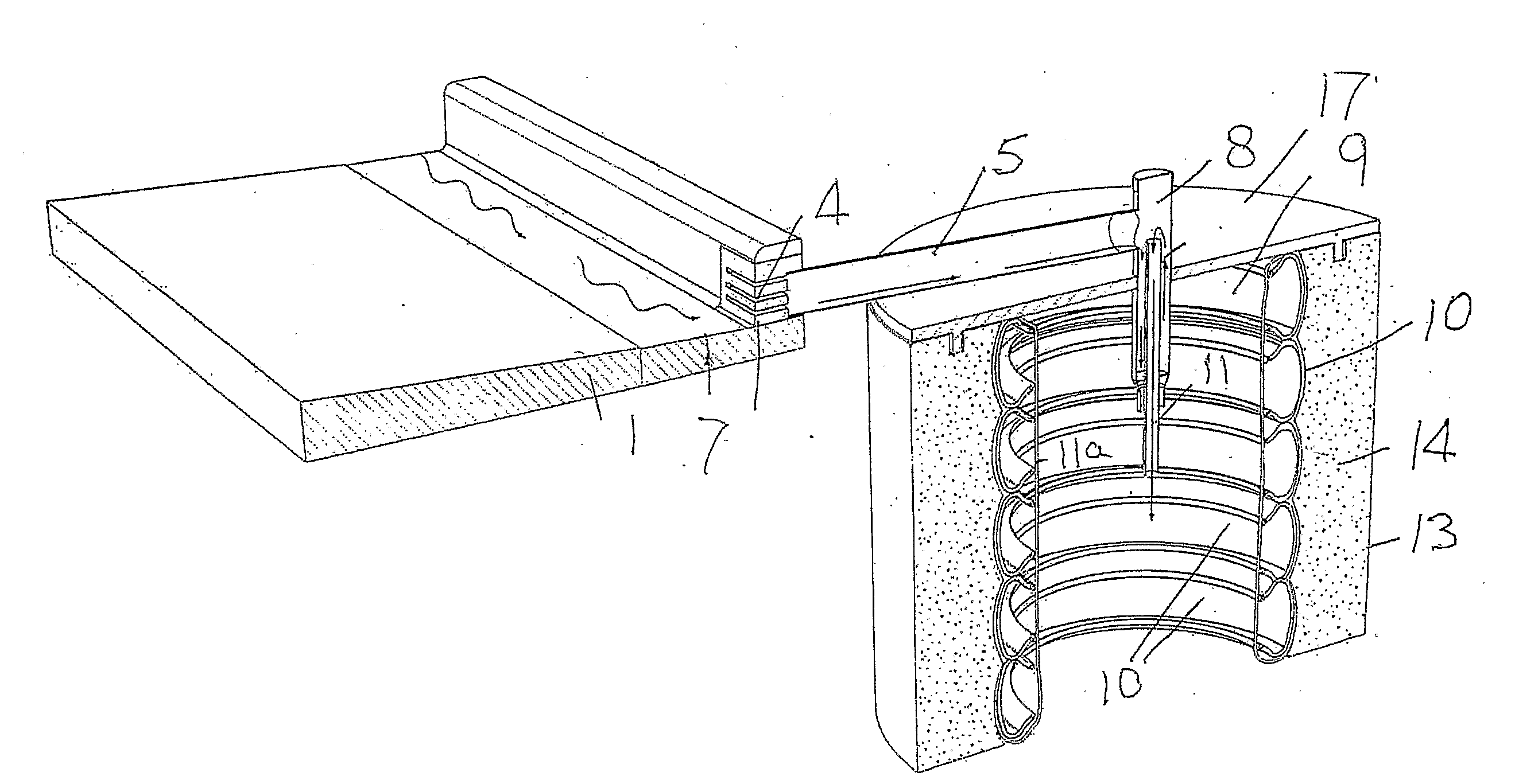
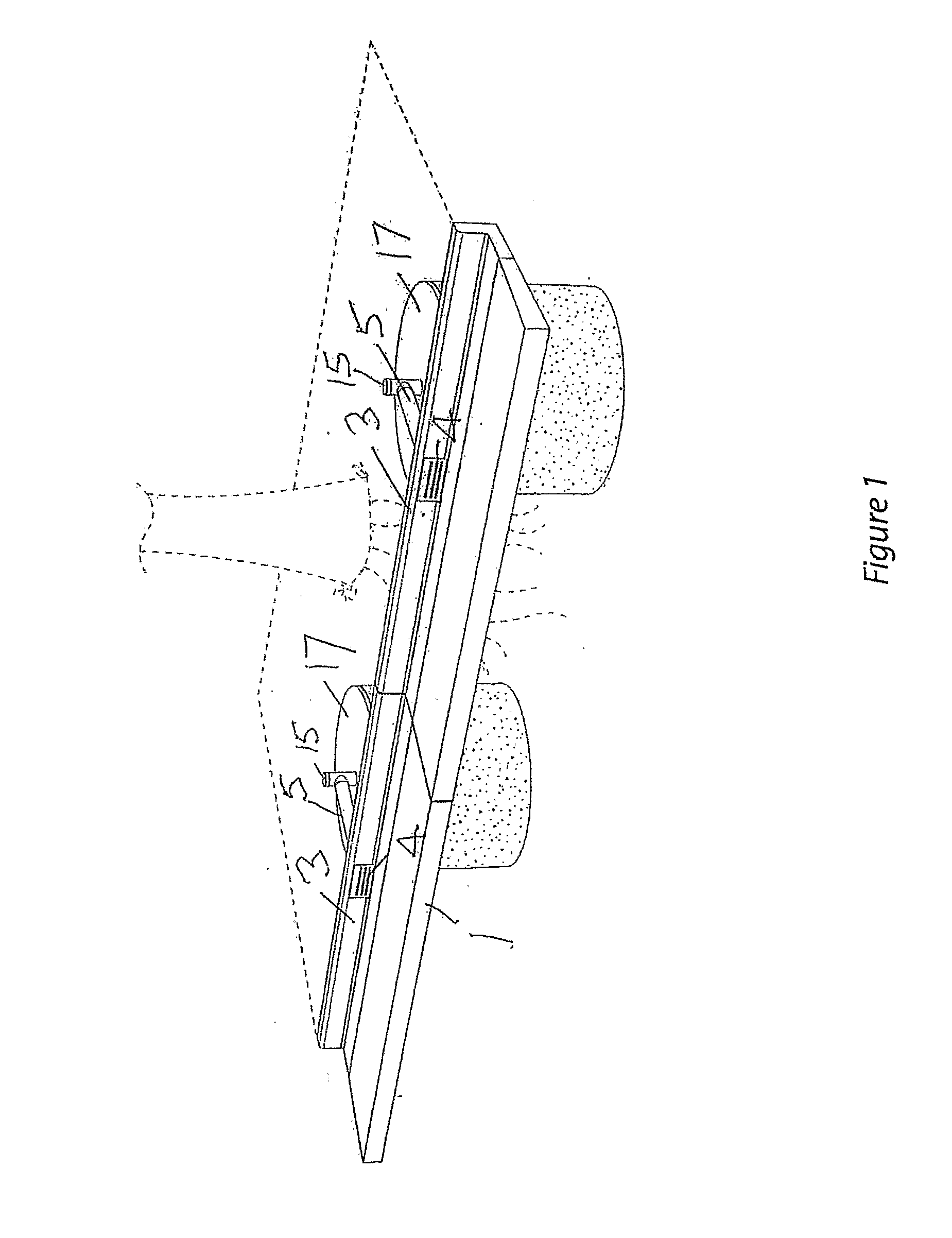
[0051]An installation or arrangement according to this embodiment is to be associated with a made surface such as at 1 which could be a road, a parking lot, a further pathway or similar.
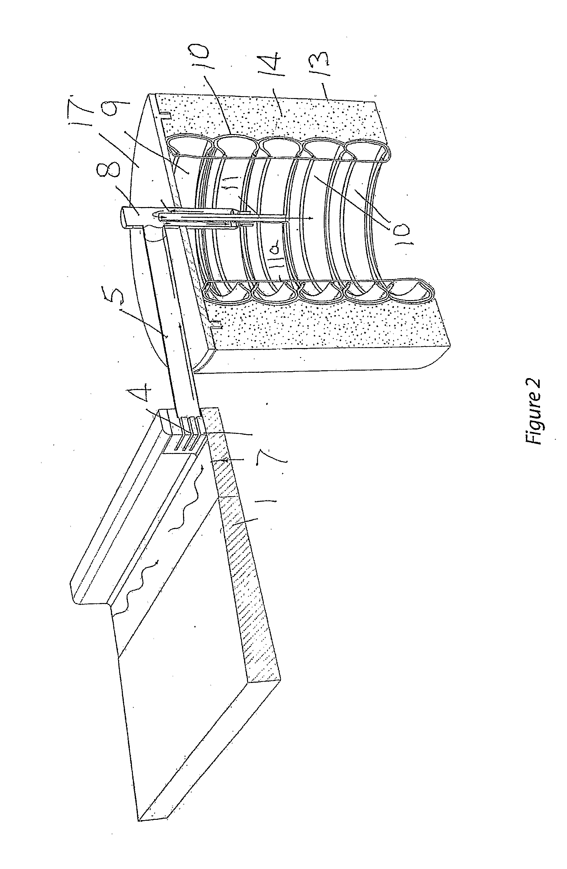
[0052]We have made kerbing providing a gutter with a kerb 3 which has three parallel apertures passing therethrough at 4, each of the apertures being positioned to extend horizontally so that a front face is provided where sticks and stone and leaves that would normally be washed down the gutter 2 will continue to pass by and will not be directly impeded by the shape of the slots but water will pass through these and pass into downwardly sloping conduit 5.
[0053]A lower one of the slots 4 at 6 is positioned above a floor level 7 of the gutter so as to avoid a lot of the finer sediment sands and like that might otherwise pass into the collection arrangement.
[0054]The downwardly sloping conduit 5 is directed to a vertical conduit 8 which is positioned so as to extend into an inner chamber 9 which is def...
PUM
 Abstract
Description
Claims
Application Information