
Method for cleaning hydraulic liquid, computerprogram product, control unit, and industrial truck
- Summary
- Abstract
- Description
- Claims
- Application Information
AI Technical Summary
Benefits of technology
Problems solved by technology
Method used
Image

Examples
Embodiment Construction
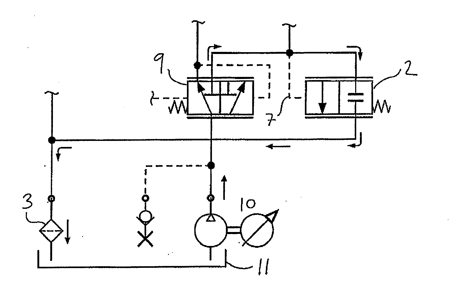
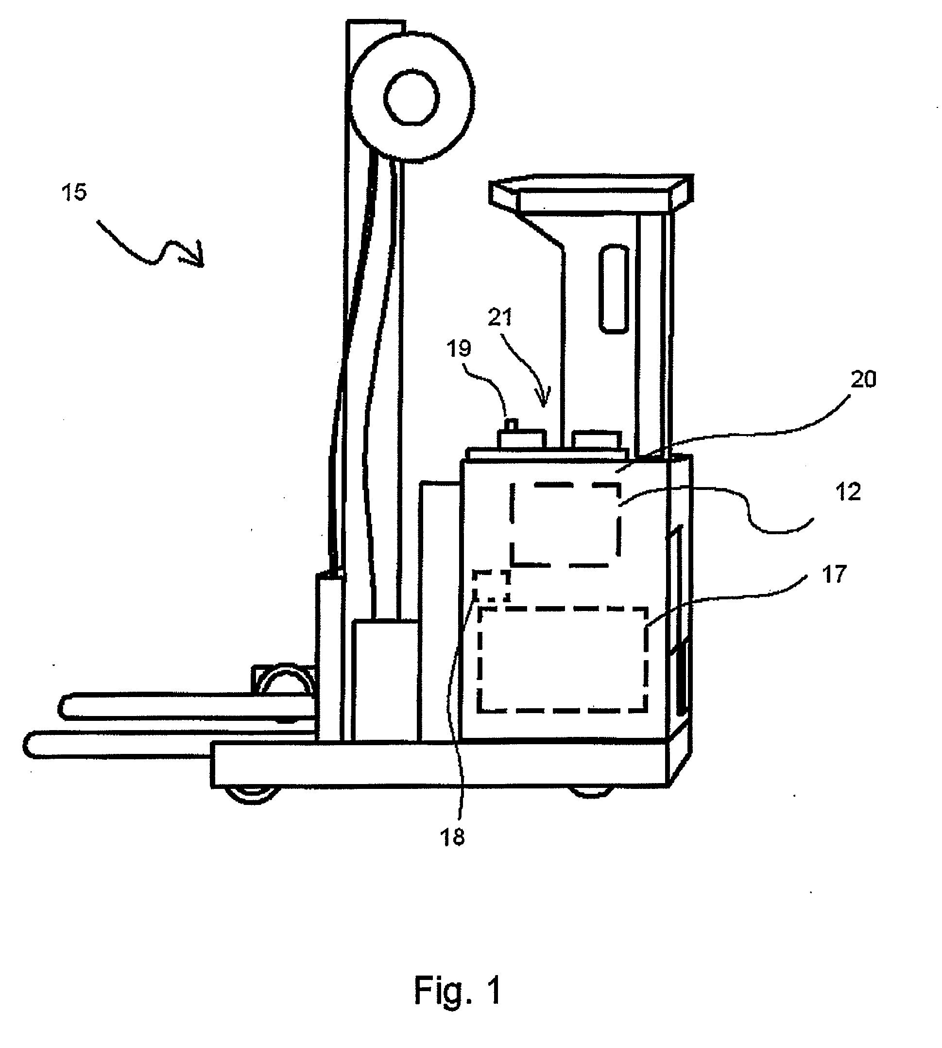
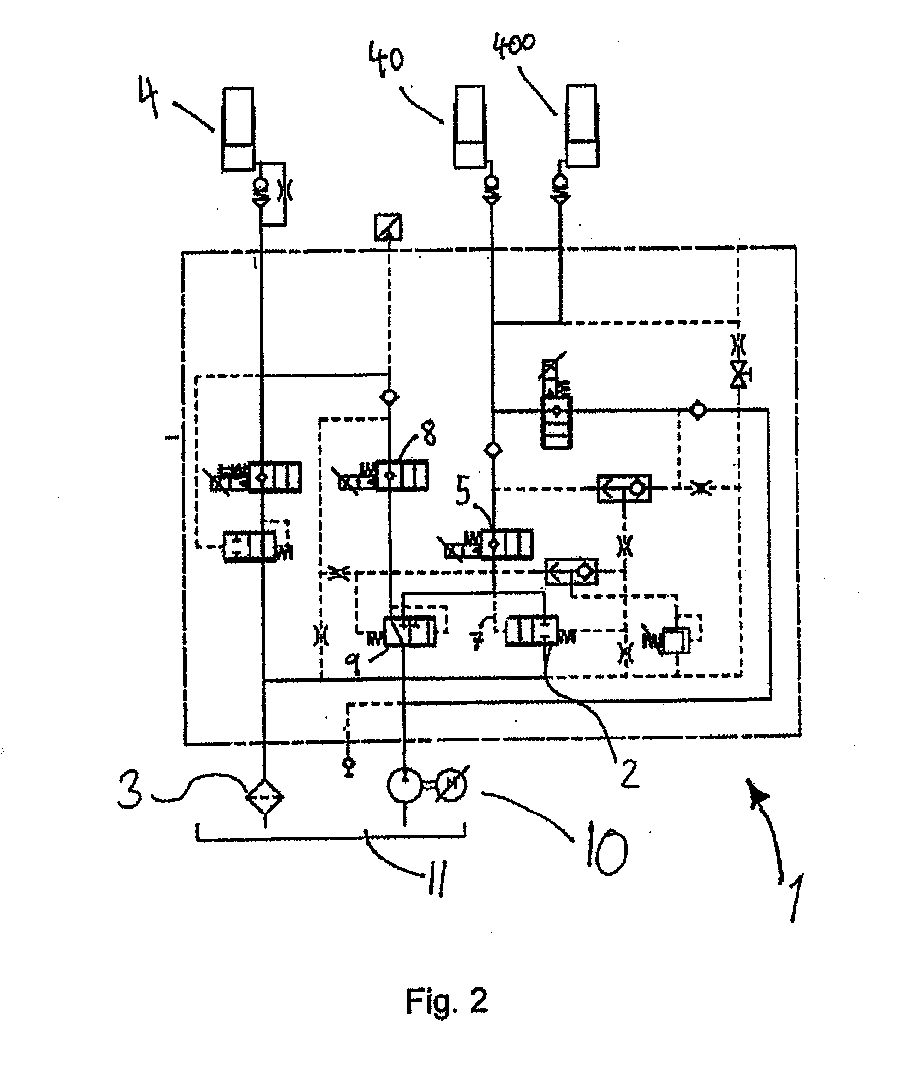
[0047]The invention is now described according to the annexed drawings. The method according to the invention consists of performing cleaning of the hydraulic liquid in an industrial truck 15, see FIG. 1. The cleaning is performed by introducing circulation of the hydraulic liquid when hydraulic activity is not present. This occurs by arranging the industrial truck 15 with means for performing this. The industrial truck 15 comprises a hydraulic pump 10, a hydraulic reservoir 11, and a return pipe to the hydraulic reservoir 11. On the return pipe a return filter 3 is positioned. The industrial truck is an electrically powered industrial truck 15 having a battery 17 as an energy source
[0048]The steps of the method is given by the known process for step a and b, where[0049]a. The hydraulic pump 10 is activated for hydraulic activity[0050]b. The hydraulic pump 10 pumps the hydraulic liquid for the hydraulic activity and in relation to this return flow occurs through the return filter 3 ...
PUM
| Property | Measurement | Unit |
|---|---|---|
| Content | aaaaa | aaaaa |
| Purity | aaaaa | aaaaa |
Abstract
Description
Claims
Application Information