Centrifugal pump assembly

Active Publication Date: 2011-07-28
GRUNDFOS MANAGEMENT AS
View PDF14 Cites 4 Cited by
  • Summary
  • Abstract
  • Description
  • Claims
  • Application Information

AI Technical Summary

Benefits of technology

[0028]The centrifugal pump extends preferably concentrically to the container and is inserted in the axial direction, i.e. in the direction of the longitudinal axis or rotation axis of the centrifugal pump, from the open end-side, into the container. Thereby, the container is preferably releasably connected to the motor housing of the drive motor, for example by way of a screwed flange connection. This permits the container and the motor housing to be able to be separated from one another, wherein then the drive motor with the centrifugal pump assembly may be removed from the container or pulled out of this, for example in order to service or exchange the centrifugal pump or the drive motor. Inasmuch as this is concerned, as very simple servicing and, as the case may be, a simple repair is possible, since all connection conduits for the conne

Problems solved by technology

The arrangement of the thrust bearing in this region usually results in the problem of the

Method used


Image

  • Centrifugal pump assembly
  • Centrifugal pump assembly
  • Centrifugal pump assembly

Examples


Example

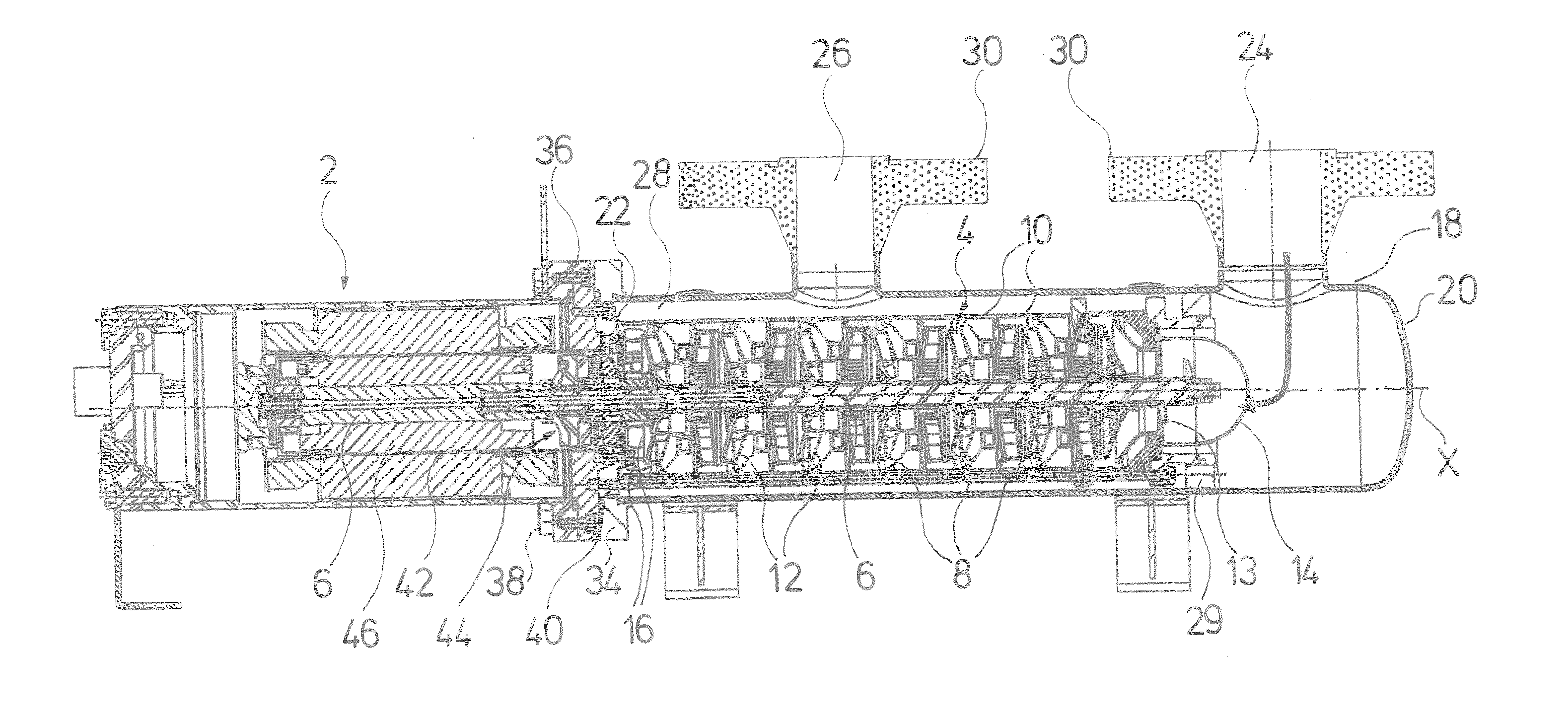
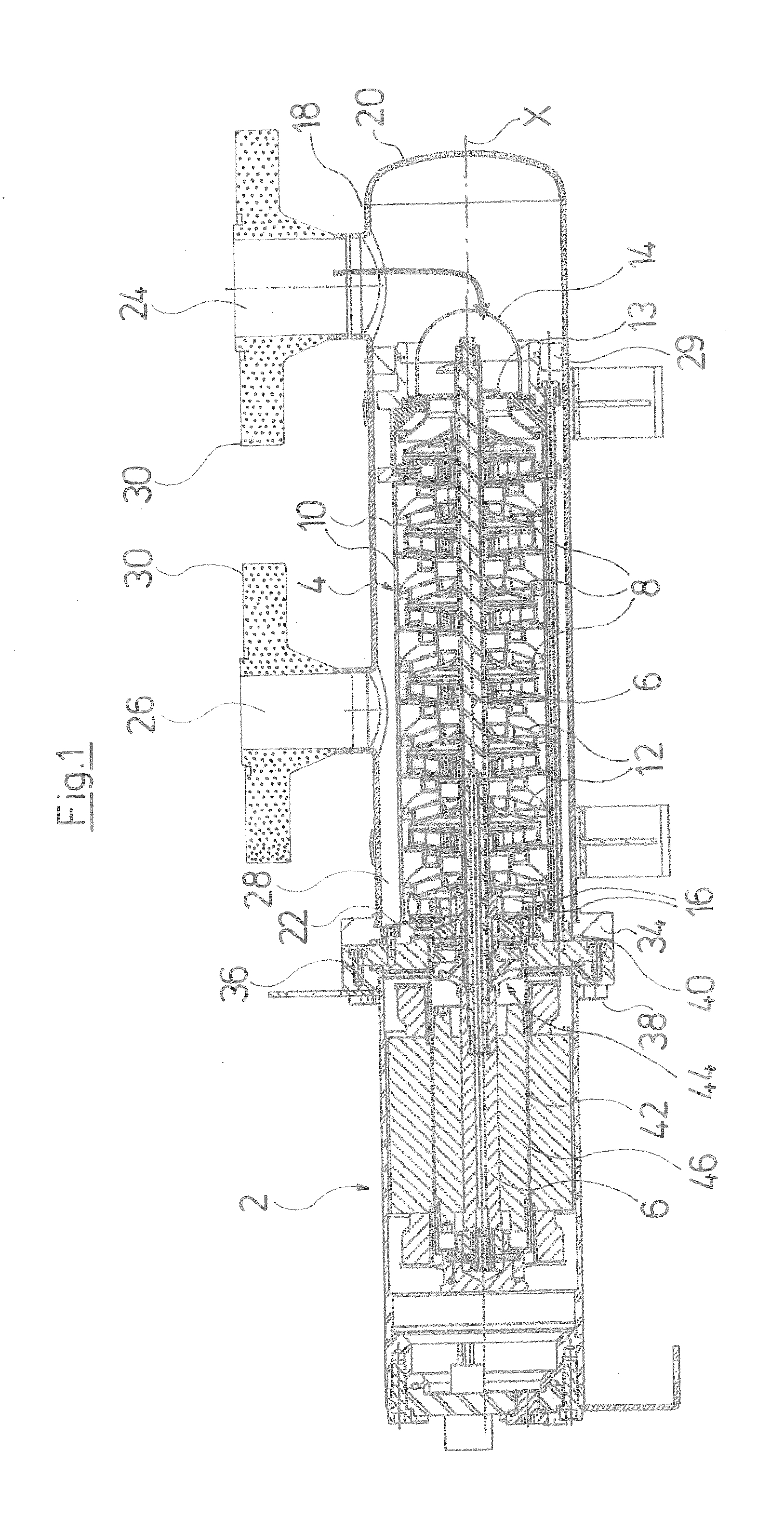
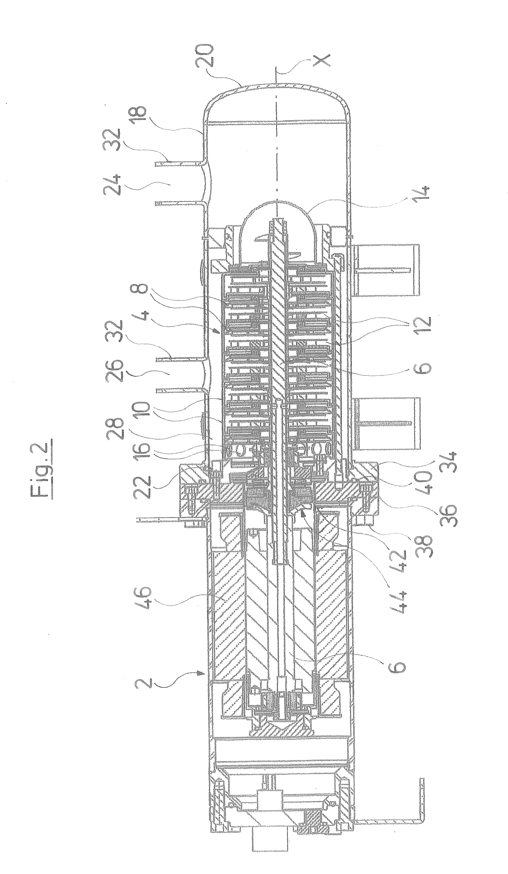
[0042]Certain terminology is used in the following description for convenience only and is not limiting. The words “front” and “rear” designate directions in the drawings to which reference is made. The word “inwardly” refers to a direction toward the geometric center of the assembly, and designated parts thereof, in accordance with the present invention. Unless specifically set forth herein, the terms “a,”“an” and “the” are not limited to one element, but instead should be read as meaning “at least one.” The terminology includes the words noted above, derivatives thereof and words of similar import.

[0043]Referring to the drawings in detail, wherein like numerals indicate like elements throughout the several views, the centrifugal pump assemblies shown in the FIGS. 1 and 2 are designed especially for the delivery of refrigerants and at an axial end comprise a drive motor 2 onto which a centrifugal pump 4 is applied at the axial side, i.e. in the direction of the rotation axis X. The...


PUM


Abstract

A centrifugal pump assembly with at least one impeller (8) and with a thrust bearing (44) which includes a rotating (50) and a stationary (48) bearing part. The rotating (50) as well as the stationary (48) bearing part are designed in a self-aligning manner.

Description

BACKGROUND OF THE INVENTION[0001]The present invention relates to a centrifugal pump assembly according to the preamble of the independent claim(s).[0002]Centrifugal pump assemblies usually comprise an electrical drive motor and a centrifugal pump which is applied thereon and which may be designed in a single-stage or multi-stage manner. The impeller or impellers of the centrifugal pump are arranged on a shaft which is connected to the drive motor. In operation of the centrifugal pump assembly, an axial force acts on the shaft as a result of the reaction force of the delivered fluid, and this axial force must be accommodated by a thrust bearing. Thereby, there are several possibilities with regard the arrangement of such a thrust bearing. The thrust bearing may be arranged at the end of the shaft but also in the middle region of the shaft, which is advantageous with certain pumps.[0003]With the arrangement in the middle region, there is the problem that alignment inaccuracies betwee...

Claims


Application Information

Patent Timeline
IPC IPC(8): F01D25/16
CPCF04D29/0413F16C17/04F16C17/06F16C23/048H02K7/083F16C33/1065F16C33/108H02K5/128F16C33/043F16C2360/44
Inventor RASMUSSEN, BJARNE DINDLERMONSTER, PETERDANIELSEN, CARL-CHRISTIAN
Owner GRUNDFOS MANAGEMENT AS
Why Eureka
Try Eureka