
Modular continuous adhesive foam mixer

a technology of adhesive foam mixer and module, which is applied in the direction of mixer, rotary stirring mixer, transportation and packaging, etc., can solve the problems of requiring extensive repairs, extending down-time on the manufacturing line, and failing prior art devices, so as to increase the number of mixing pins and surface area, effective and efficient mixing of adhesive compound, and easy to repair

Active Publication Date: 2020-03-24
ELLIS MICHAEL A
View PDF18 Cites 0 Cited by
  • Summary
  • Abstract
  • Description
  • Claims
  • Application Information

AI Technical Summary

Benefits of technology

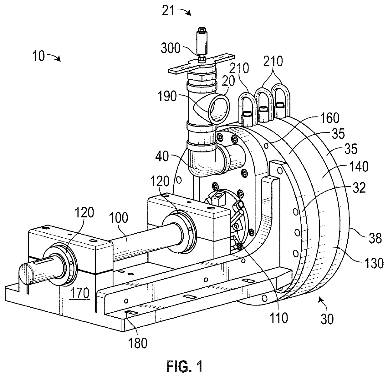
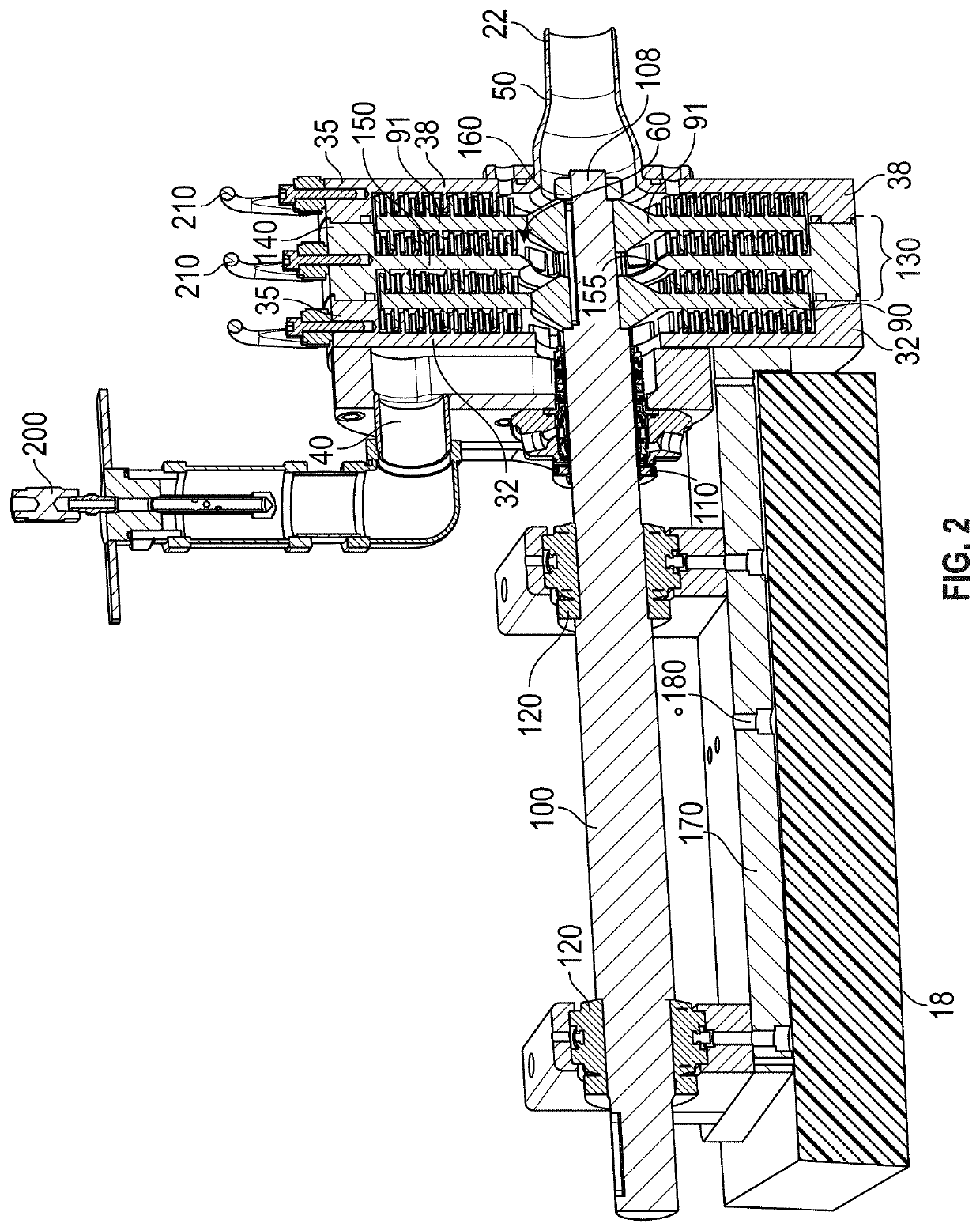
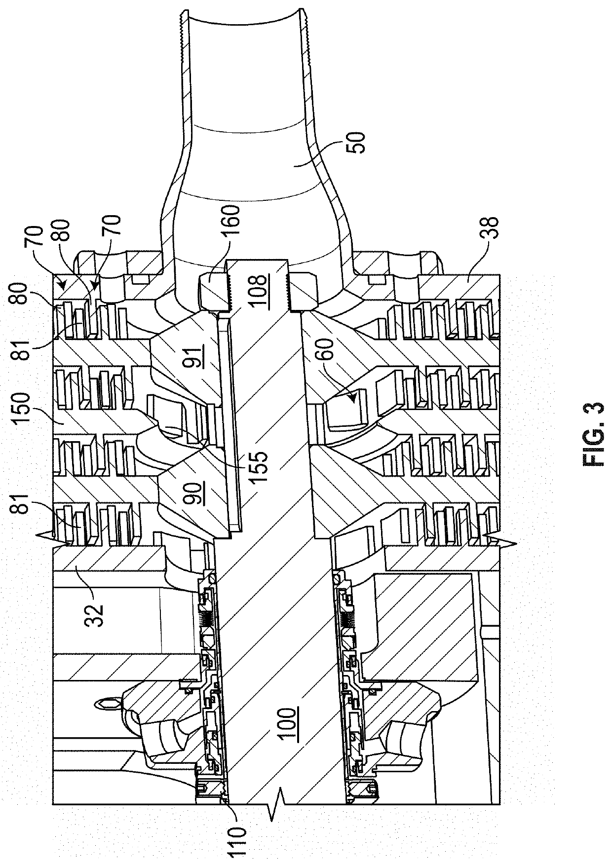
The present invention is a device that efficiently mixes adhesive compound and air to create adhesive foam. It is modular, meaning additional parts can be added to increase the mixing capacity and performance as needed. The device is easy to repair in the field, requires minimal downtime, and includes features to prevent incorrect assembly. It can also have multiple rotor disks to increase throughput and a relatively large mixing volume for better foam structure and motor life. The mixer is simple to disassemble and service, and made in a way that prevents damage to the moving parts. Overall, the present invention is a more efficient, effective, and easy-to-use device for mixing adhesive compound and air to create foam.

Problems solved by technology

Prior art devices are notorious for failing during, often requiring extensive repairs and extended down-time on the manufacturing line.
Further, multiple such prior art devices are often needed to obtain a suitable level of mixing of the adhesive compound with air to generate the adhesive foam, which is expensive.

Method used


Image

  • Modular continuous adhesive foam mixer
  • Modular continuous adhesive foam mixer
  • Modular continuous adhesive foam mixer

Examples


Embodiment Construction

[0016]Illustrative embodiments of the invention are described below. The following explanation provides specific details for a thorough understanding of and enabling description for these embodiments. One skilled in the art will understand that the invention may be practiced without such details. In other instances, well-known structures and functions have not been shown or described in detail to avoid unnecessarily obscuring the description of the embodiments.

[0017]Unless the context clearly requires otherwise, throughout the description and the claims, the words “comprise,”“comprising,” and the like are to be construed in an inclusive sense as opposed to an exclusive or exhaustive sense; that is to say, in the sense of “including, but not limited to.” Words using the singular or plural number also include the plural or singular number respectively. Additionally, the words “herein,”“above,”“below” and words of similar import, when used in this application, shall refer to this appli...


PUM

PropertyMeasurementUnit
Volumeaaaaaaaaaa
Surface areaaaaaaaaaaa

Abstract

A modular continuous mixer includes a rigid casing having an inlet adjacent to an annular inlet end thereof and an outlet adjacent an opposing annular outlet end thereof. The casing further includes a cylindrical exterior casing wall that, together with the ends, define a volume therein. The ends each include a plurality of concentric rings of mixing pins projecting into the volume. One or more rotor disks are rotationally fixed within the casing between distal ends of the opposing pins. Each rotor disk includes a plurality of the concentric rings of mixing pins projecting from both sides thereof toward the inlet and outlet ends. A drive shaft is rotatably mounted in the casing and fixed through the center of each rotor disk. Additional casing extensions can be mounted between the inlet and outlet ends of the casing to facilitate further mixing.

Description

CROSS-REFERENCE TO RELATED APPLICATIONS[0001]This application claims the benefit of U.S. Provisional Patent Application 62 / 325,987, filed on Apr. 21, 2016, and incorporated herein by reference.STATEMENT REGARDING FEDERALLY SPONSORED RESEARCH AND DEVELOPMENT[0002]Not Applicable.FIELD OF THE INVENTION[0003]This invention relates to mixing devices, and more particularly to a modular latex adhesive foam generator.DISCUSSION OF RELATED ART[0004]Adhesive foam mixers are known in the art for mixing adhesive foam compounds for use with carpet manufacturing. Prior art devices are notorious for failing during, often requiring extensive repairs and extended down-time on the manufacturing line. Further, multiple such prior art devices are often needed to obtain a suitable level of mixing of the adhesive compound with air to generate the adhesive foam, which is expensive.[0005]Therefore, there is a need for a device that effectively and efficiently mixes the adhesive compound and air to create t...

Claims


Application Information

Patent Timeline
IPC IPC(8): B01F7/00B01F3/04B01F7/10B01F27/73
CPCB01F3/04453B01F7/10B01F7/0045B01F7/00633B01F7/00841B01F2215/006B01F23/2351B01F27/2711B01F2101/36B01F27/276B01F27/73B01F27/115B01F27/191
Inventor ELLIS, MICHAEL A.
Owner ELLIS MICHAEL A
Learn More