Elevator

a technology of elevators and lowering wheels, applied in the field of elevators, can solve the problems of sudden changes in vertical forces exerted on the car, uncontrollable change of the load of the car, rapid stepwise movement of the car upwards or downwards, etc., and achieve the effect of limiting the movement speed of the tightening wheel, and substantially eliminating the risk of the car during the unloading situation

Active Publication Date: 2018-01-02
KONE CORP
View PDF12 Cites 2 Cited by
  • Summary
  • Abstract
  • Description
  • Claims
  • Application Information

AI Technical Summary

Benefits of technology

[0009]It is brought forward a new elevator, which comprises a hoistway, an elevator car vertically movable in the hoistway, a counterweight vertically movable in the hoistway and at least one tightening wheel located in the lower end of the hoistway. The elevator further comprises at least one rope wheel located in or at least in proximity of the upper end of the hoistway and a first roping interconnecting the car and counterweight and passing around the at least one rope wheel located in or at least in proximity of the upper end of the hoistway, and suspending the car and counterweight on opposite sides of said rope wheel. The elevator further comprises a second roping interconnecting the car and counterweight and passing around the at least one tightening wheel, the tightening wheel being mounted movably back and forth in a first direction towards the second roping, and in a second direction away from the second roping; and means for exerting force on the tightening wheel to move it in the first direction so as to tighten the second roping. The elevator further comprises means for limiting the movement speed of the tightening wheel towards the first direction and the second direction. Thereby said means are configured to allow movement of the tightening wheel towards the first direction with a limited speed as well as to allow movement of the tightening wheel towards the second direction with a limited speed. Said means thereby limit the movement speed of the tightening wheel towards the first and second direction without blocking movement towards these directions totally. As a consequence of limiting the movement speed of the tightening wheel towards the first direction, the risks of sudden movement of the car during a loading situation are substantially eliminated. A substantial part of the effects of the sudden increase in car load can thus be neutralized. Particularly a sudden stepwise sag of the car is thus eliminated. As a consequence of limiting the movement speed of the tightening wheel towards the second direction, on the other hand, the risks of sudden movement of the car during an unloading situation are substantially eliminated. A substantial part of the effects of the sudden increase in car load can thus be neutralized. Particularly a sudden stepwise lift of the car is thus eliminated. The slow response in movement (towards both of the two directions) facilitated by said limiting of the speed of the tightening wheel results in that undesired car movement can be neutralized in both of these directions, but also in that the tightening wheel can move slowly towards either one of the first direction and second direction, as optimal for the situation, such that tension in the second roping is maintained appropriate.
[0011]In a preferred embodiment the means for limiting stroke speed of the cylinder comprises a conduit system for allowing passage of hydraulic fluid to and from the hydraulic chamber during strokes of the hydraulic cylinder connected with an opening in the hydraulic chamber delimited by the piston part and the cylinder part, and one or more adjustable flow control valves in the conduit system, and in that each of the stroke in said first direction and the stroke in the second stroke direction is arranged to a change the volume of the hydraulic chamber, and to displace an amount of hydraulic fluid through said opening and through at least one of said adjustable flow control valves, which amount is equal to the amount of change of the volume of the hydraulic chamber during the stroke, the flow rate of hydraulic fluid into (during a stroke in one of the first and second stroke direction) and out of (during a stroke in the other of the first and second stroke direction) the hydraulic chamber through said opening being thereby limited by said at least one adjustable flow control valve. Thereby the stroke speed of the cylinder during each stroke is adjustably limited. With this configuration, the stroke speeds are easy to adjust. The hydraulic system is hereby also simple to dimension, implement and service.
[0014]In a preferred embodiment the means for limiting stroke speed of the cylinder comprises a conduit system for allowing passage of hydraulic fluid to or from the hydraulic chamber during said stroke of the hydraulic cylinder connected with an opening in a hydraulic chamber delimited by the piston and the cylinder, and an adjustable flow control valve in the conduit system, and in that each of the stroke in said first direction and the stroke in the second stroke direction is arranged to a change the volume (increase or decrease) of the hydraulic chamber, and to displace an amount of hydraulic fluid through said opening and said adjustable flow control valve, which amount is equal to the amount of change of the volume of the hydraulic chamber during the stroke, the flow rate of hydraulic fluid into the hydraulic chamber during a stroke in one of the first and second stroke direction, and the flow rate of hydraulic fluid into the hydraulic chamber during a stroke in the other of the first and second stroke direction being thereby limited by said (same) flow control valve. Thereby, the stroke speed of the cylinder during each stroke is adjustably limited. The hydraulic system is hereby also simple to implement and service.

Problems solved by technology

When an elevator car is parked at landing to unload and load, people tend to move within the car and between the car and the landing such that car load is uncontrollably changed.
Correspondingly, sudden lightening of the load causes sudden changes in vertical forces exerted on the car.
Unless prevented, the sudden changes in vertical forces are likely to cause rapid stepwise movement of the car upwards or downwards, or even vertical swinging of the car.
A drawback of the known elevators has been that this kind of rapid movement of the car caused during the loading and unloading has been difficult to eliminate simply and efficiently.
Such a sudden stop may be caused for example if during a run of the elevator the counterweight accidentally gets stuck on its guide rails or if the safety gear is activated, e.g. due to overspeed situation.
These types of incidents would be harmful and dangerous, because they would cause sudden jerks for the people inside the car.
The known tie-down devices generally react to extremely large one-directional shocks caused in the elevator roping system during an emergency, and they are not designed solve the problems of the loading and unloading situations.
In particular, they are not suitable to act as means for removing up and down-directed fine-scale jerks caused in the car during a normal situation, when an elevator car is parked at landing for unloading and / or loading.

Method used


Image

  • Elevator
  • Elevator
  • Elevator

Examples


Embodiment Construction

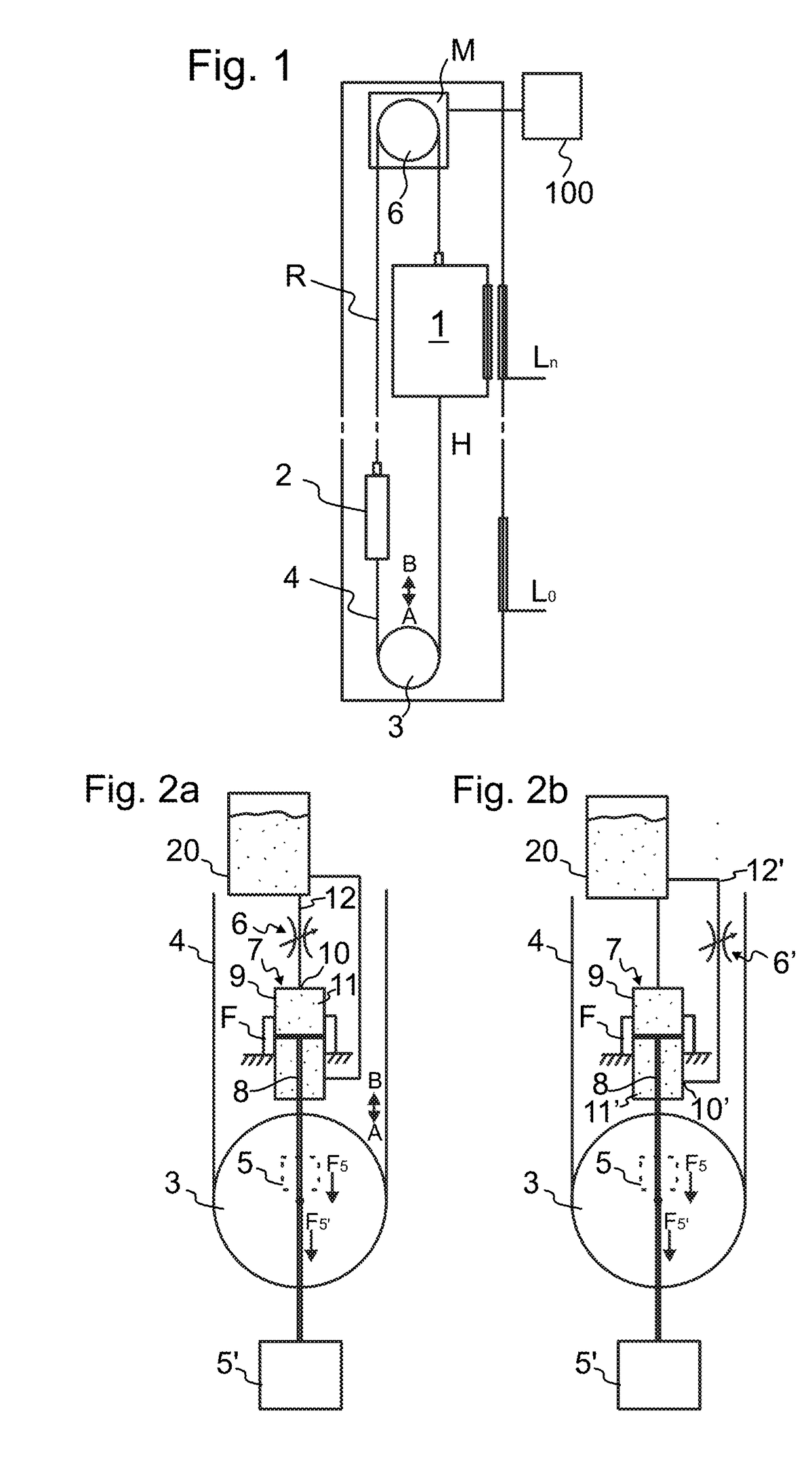
[0028]FIG. 1 illustrates an elevator according to a preferred embodiment. The elevator comprises a hoistway H, an elevator car 1 and a counterweight 2 vertically movable in the hoistway H, and a drive machine M, which provides moving force for the elevator car 1 under control of an elevator control system 100. The elevator furthermore comprises landings L0-Ln, where the elevator car is arranged to visit for unloading passengers and / or loading passengers.

[0029]The car 1 and counterweight 2 are interconnected by a first roping R, i.e. a suspension roping R, which passes around at least one rope wheel 6 located in or at least in proximity of the upper end of the hoistway H suspending the car 1 and counterweight 2 on opposite sides of the rope wheel 6.

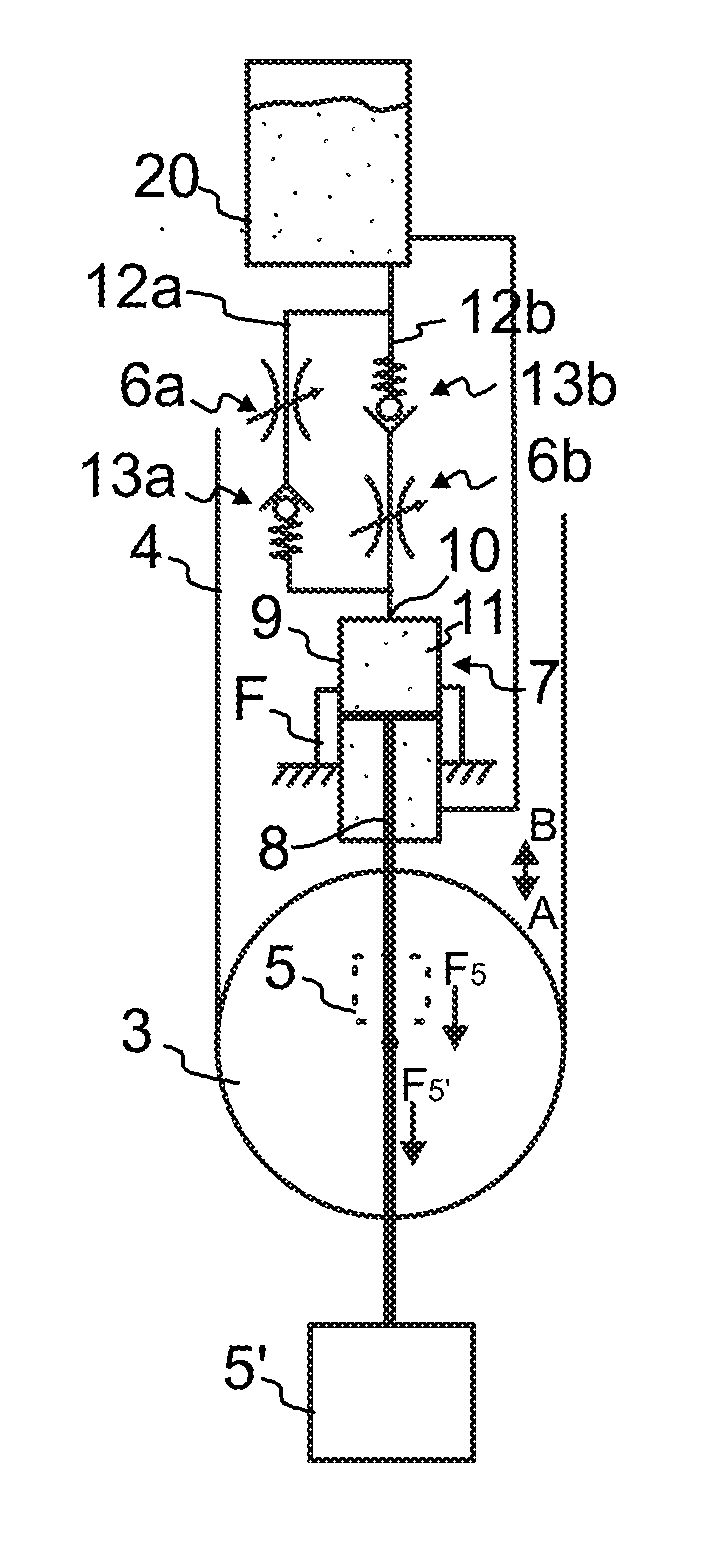
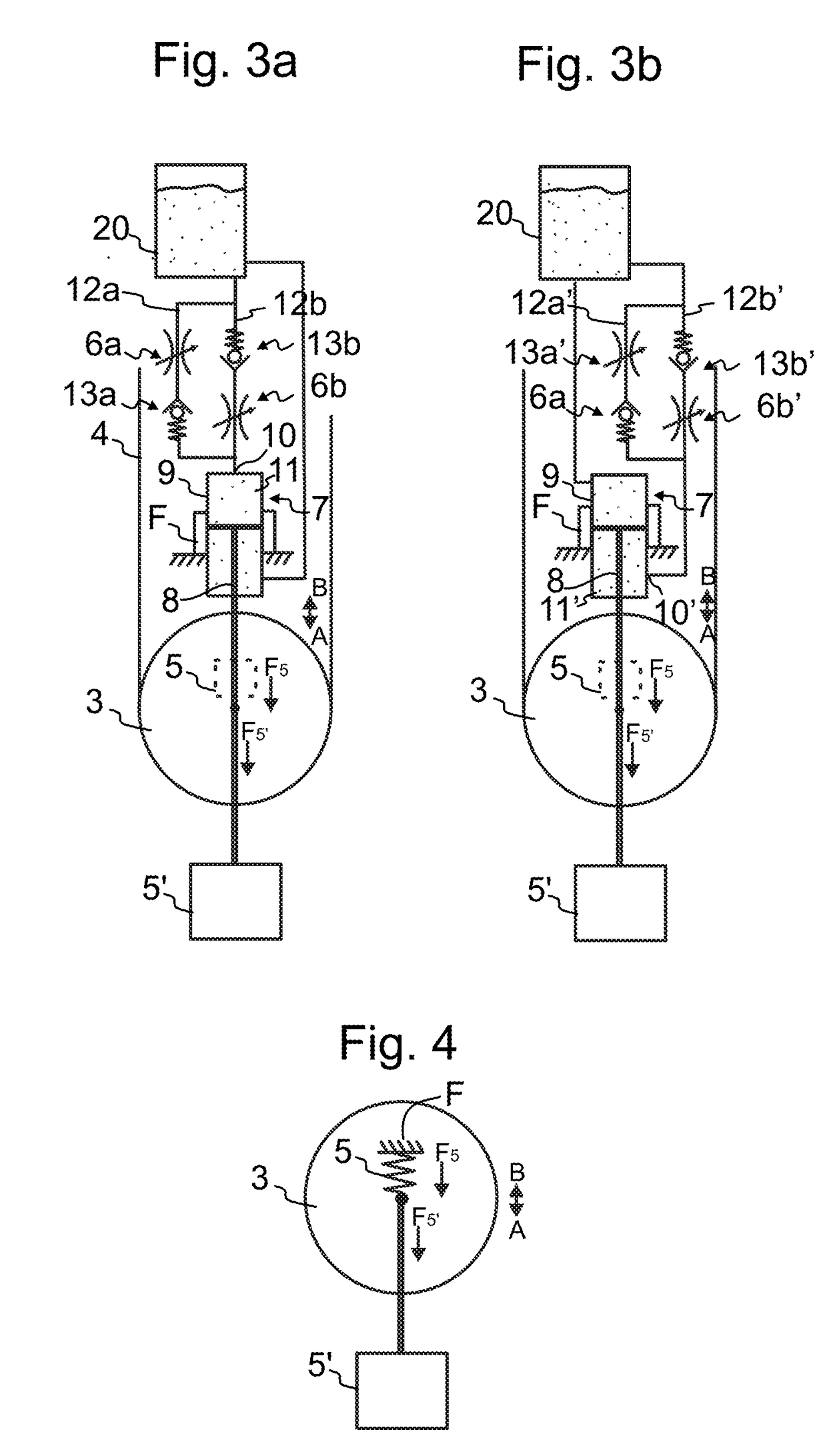
[0030]The elevator further comprises at least one tightening wheel 3 located in the lower end of the hoistway H, and a second roping 4 interconnecting the car 1 and counterweight 2 and passing around the at least one tightening wheel 3. Th...


PUM


Abstract

An elevator comprisinga hoistway;an elevator car vertically movable in the hoistway;a counterweight vertically movable in the hoistway;at least one tightening wheel located in the lower end of the hoistway;at least one rope wheel located in or at least in proximity of the upper end of the hoistway;a first roping interconnecting the car and counterweight and passing around the at least one rope wheel located in or at least in proximity of the upper end of the hoistway;a second roping interconnecting the car and counterweight and passing around the at least one tightening wheel, the tightening wheel being mounted movably back and forth in a first direction towards the second roping, and in a second direction away from the second roping; andmeans for exerting force on the tightening wheel to move it in the first direction so as to tighten the second roping.The elevator further comprises means for limiting the movement speed of the tightening wheel towards the first direction and the second direction.

Description

[0001]This application claims priority to European Patent Application No. EP14164857.6 filed on Apr. 16, 2014, the entire contents of which are incorporated herein by reference.FIELD OF THE INVENTION[0002]The invention relates to an elevator. The elevator is particularly meant for transporting passengers and / or goods.BACKGROUND OF THE INVENTION[0003]Elevators typically have a suspension roping between the elevator car and the counterweight which roping passes around a rope wheel mounted stationary in some suitable position above said elevator units. Additionally, the elevator may need to be provided with a second roping between the elevator car and the counterweight suspended to hang from the elevator car and the counterweight. This type of arrangement is normally used to provide compensation for the weight of the hoisting roping. Particularly, in this way the unbalance caused by the hoisting roping and occurring when the elevator car is run to its extreme position can be eliminated...

Claims


Application Information

Patent Timeline
Patent Type & Authority Patents(United States)
IPC IPC(8): B66B7/06B66B7/10
CPCB66B7/068
Inventor LAMPINEN, RIKU
Owner KONE CORP
Why Eureka
Try Eureka