
Method and apparatus for image forming capable of effectively reducing unevenness of density and color displacement of images

a technology of color displacement and image, applied in the field of method and apparatus for image forming, can solve the problems of uneven density, inability to prevent unevenness, and difficulty in concentrating all of these components with each other, and achieve the effect of effective reducing the uneven density and color displacement of images and high precision

Active Publication Date: 2005-03-10
RICOH KK
View PDF69 Cites 53 Cited by
  • Summary
  • Abstract
  • Description
  • Claims
  • Application Information

AI Technical Summary

Benefits of technology

[0041] In view of the foregoing, it is an object of the present invention to provide a novel method and apparatus capable of effectively reducing unevenness of density and color displacement of images by controlling a speed of a transfer member with high precision.

Problems solved by technology

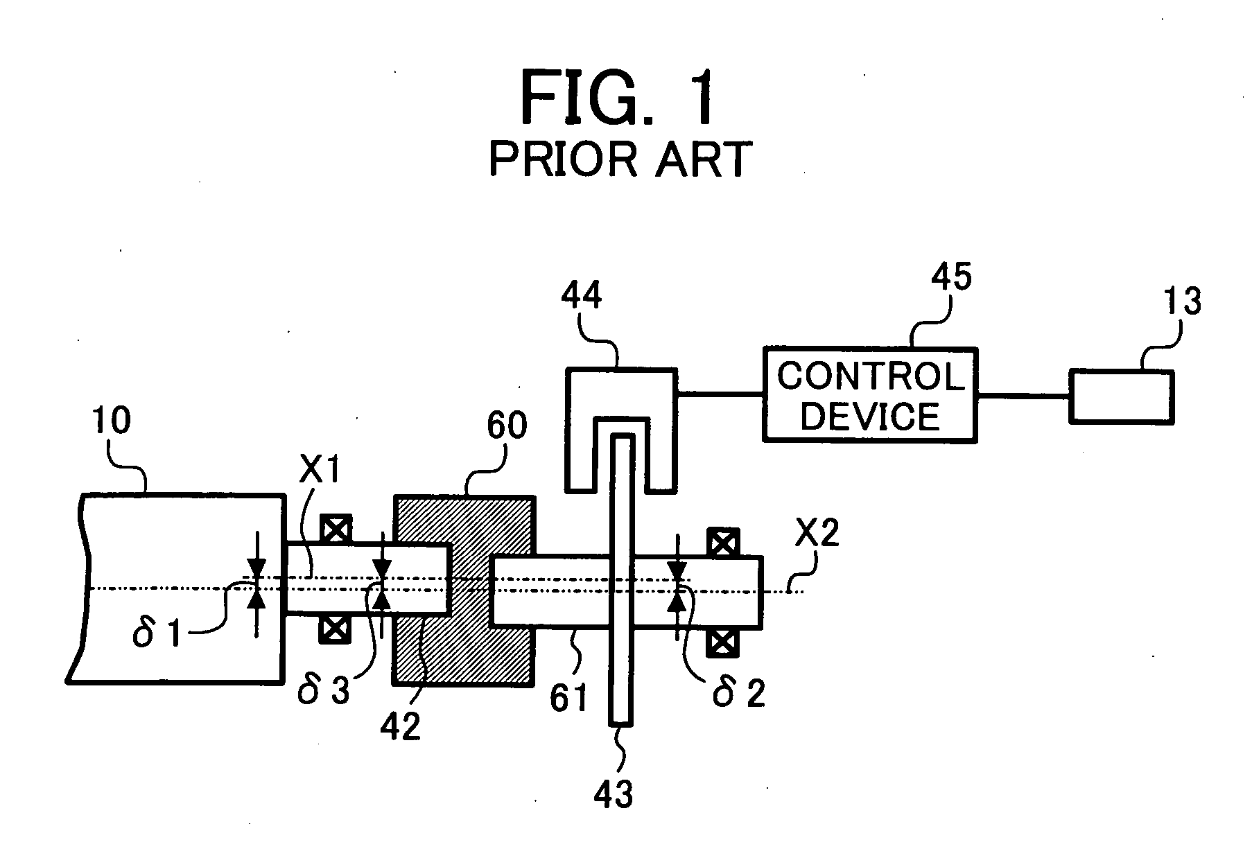
Therefore, if the variation in speed of the moving member caused by an eccentricity of the support shaft is eliminated by a control of the drive motor, the variation in speed of the transfer belt inadvertently occurs, thus the unevenness of density occurs in the toner image transferred to the recording sheet from the image carrying member or from the intermediate transfer belt.
However, the above-described detecting mechanism has drawbacks as follows.
However, it is difficult to couple all of these components concentrically with each other.
Therefore, the above-described configuration cannot prevent the unevenness of density of each toner image transferred to the recording sheet from each of the image carrying members or the intermediate transfer belt.
Such unevenness of density becomes more significant when the above-mentioned eccentricities are accumulated.
Consequently, the unevenness of density is likely to occur in the toner image transferred to the recording sheet from the image carrying members or the intermediate transfer belt.
In addition, when a plurality of color images are not overlayed correctly in an image forming apparatus a color displacement will occur, and degrade an image quality.

Method used


Image

  • Method and apparatus for image forming capable of effectively reducing unevenness of density and color displacement of images
  • Method and apparatus for image forming capable of effectively reducing unevenness of density and color displacement of images
  • Method and apparatus for image forming capable of effectively reducing unevenness of density and color displacement of images

Examples


Embodiment Construction

[0088] In describing preferred embodiments illustrated in the drawings, specific terminology is employed for the sake of clarity. However, the disclosure of the present patent specification is not intended to be limited to the specific terminology so selected and it is to be understood that each specific element includes all technical equivalents that operate in a similar manner.

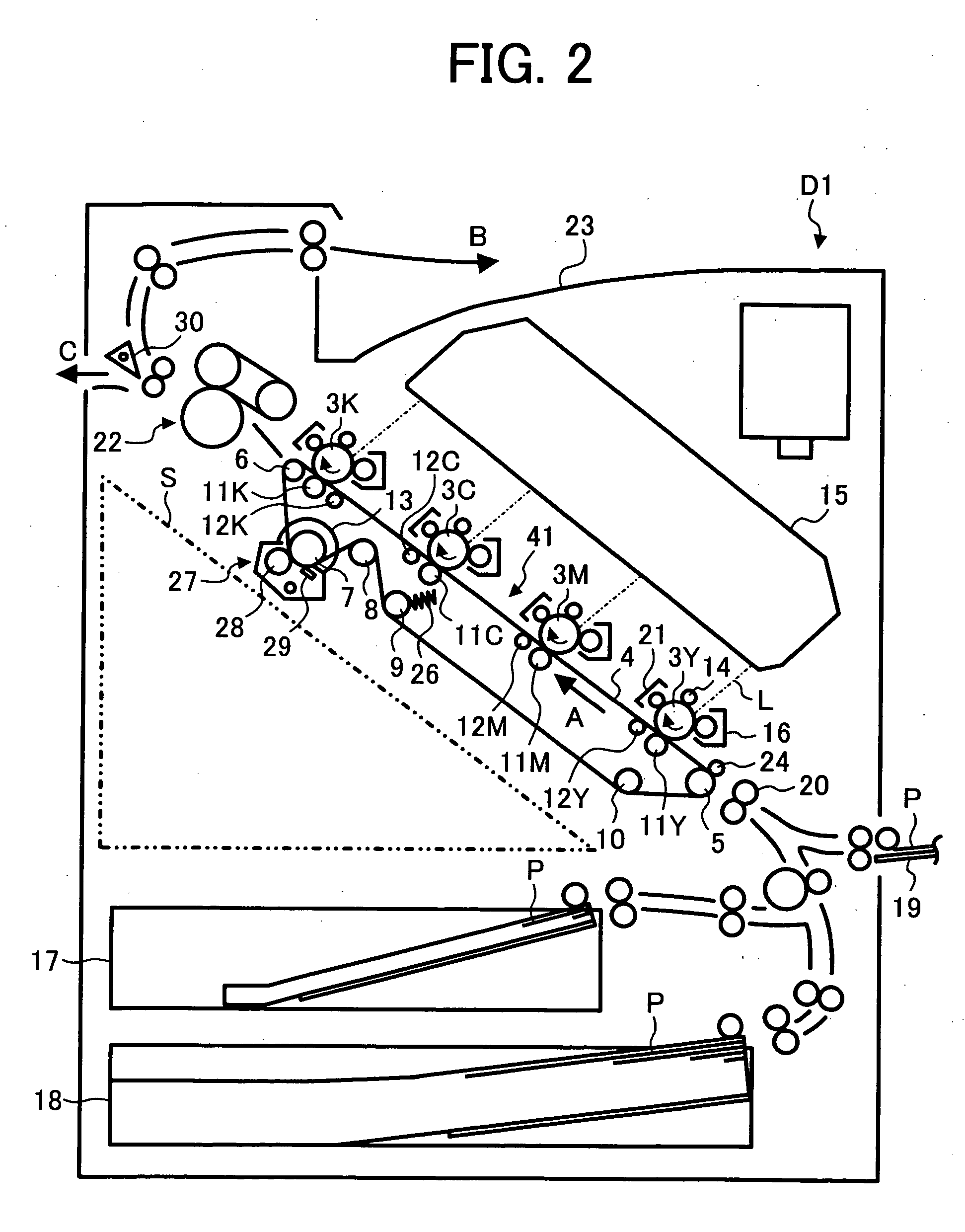
[0089] Referring now to the drawings, wherein like reference numerals designate identical or corresponding parts throughout the several views, and more particularly to FIG. 2 thereof, an exemplary image forming apparatus according to an exemplary embodiment of the present invention is described.

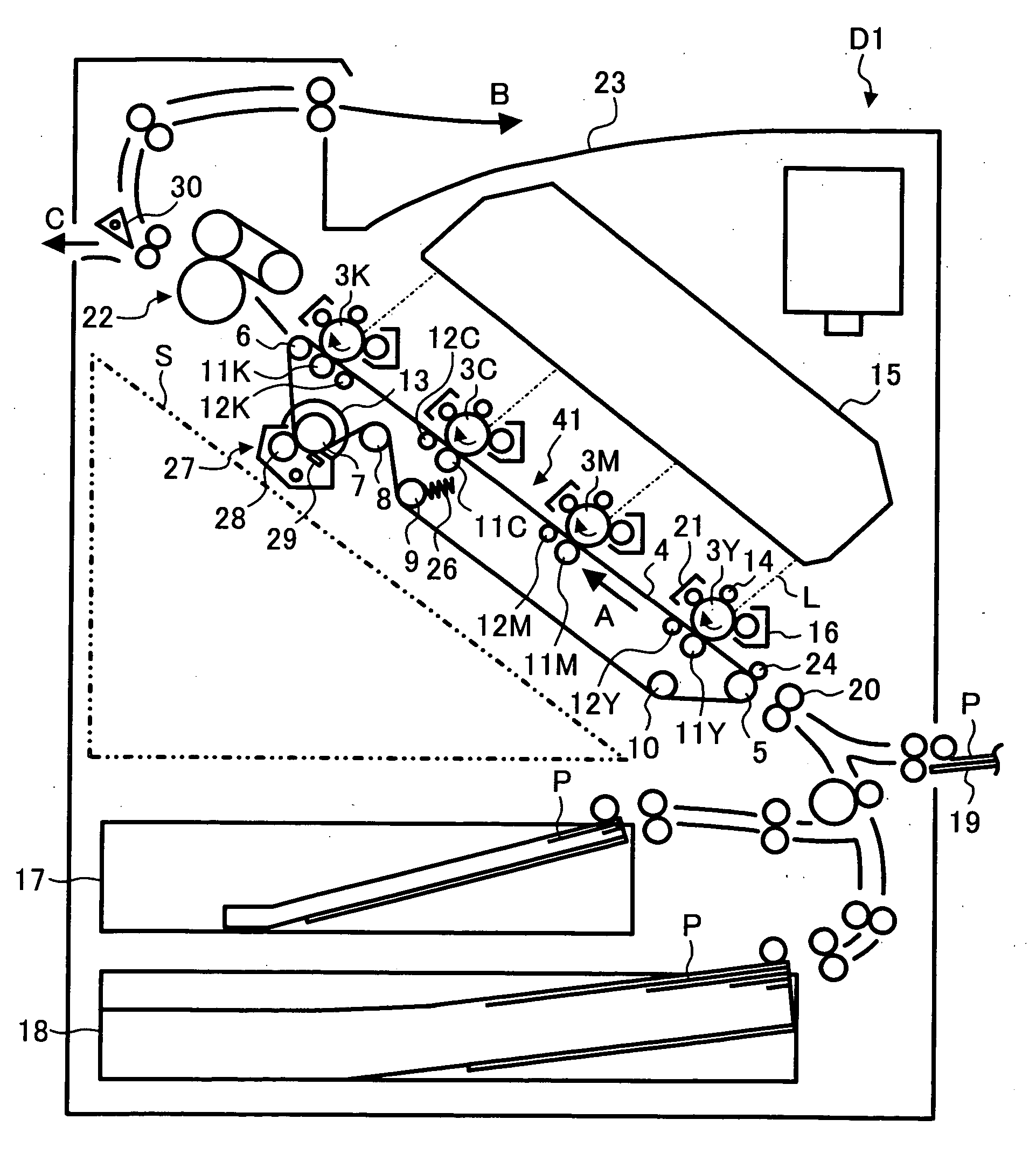
[0090]FIG. 2 is a schematic drawing of an image forming apparatus using a direct transfer method.

[0091] The image forming apparatus includes a plurality of image carrying members 3Y, 3M, and 3C, and 3K installed in a body D1 of the image forming apparatus, and each of the image carrying members 3Y, 3M, and 3C, and ...


PUM


Abstract

An image forming apparatus including an image carrying member, a transfer member, support rollers, a detecting mechanism, and a controller. The image carrying member forms a toner image on its surface facing a surface of the transfer member, supported by the support rollers, which transfers the toner image to a recording medium. The detecting mechanism includes a detection roller, a roller shaft, a moving member, and a sensor, and detects a speed of the transfer member. The detection roller includes one support roller selected from the support rollers, and is provided with the roller shaft. The moving member is directly fixed to the roller shaft and rotates with the detection roller. The sensor detects a moving speed of the detection roller with the moving member. The controller controls a traveling speed of the transfer member to a target speed based on a detection result of the sensor.

Description

BACKGROUND OF THE INVENTION [0001] 1. Field of the Invention [0002] The present invention relates to a method and apparatus for image forming, and more particularly to a method and apparatus for image forming capable of effectively reducing unevenness of density and color displacement of images by controlling a speed of a transfer member with a high precision. [0003] 2. Discussion of the Background [0004] Conventionally, image forming apparatuses are widely used and known for electro-photo graphic copiers, printers, and facsimiles, or for composite machines having at least one functional combination among electro-photo graphic copier, printer, and facsimile. [0005] For example, an image forming apparatus using a direct transfer method or an intermediate transfer method are widely known. [0006] In the direct transfer method, toner images of each color formed on a plurality of image carrying members are overlayingly transferred to a recording sheet carried and transported on a sheet t...

Claims


Application Information

Patent Timeline
Patent Type & Authority Applications(United States)
IPC IPC(8): G03G15/16
CPCG03G15/1625G03G2215/1623G03G2215/0158G03G2215/0119
Inventor YOKOYAMA, MASATOYOKOKAWA, NOBUTOANDO, TOSHIYUKIKOBAYASHI, KAZUHIKOSHINOHARA, TADASHIMATSUDA, YUUJIHOSOKAWA, JUNMIURA, YOHHEITAKAHASHI, TOSHIYUKIMATSUDA, HIROMICHI
Owner RICOH KK
Learn More