Liquid crystal display device

a liquid crystal display and display device technology, applied in the field of liquid crystal display devices, can solve the problems of uneven mixed degradation of the display quality of the liquid crystal display device, uneven mixing color of red, green and blue, etc., and achieve the effect of reducing the thickness of the display device and the size of the display fram

Inactive Publication Date: 2009-05-07
SHARP KK
View PDF5 Cites 17 Cited by
  • Summary
  • Abstract
  • Description
  • Claims
  • Application Information

AI Technical Summary

Benefits of technology

[0015]In order to overcome the problems described above, preferred embodiments of the present invention provide a liquid crystal display device that achieves reduction in the thickness thereof and the size of its frame while reducing color unevenness even when single color LEDs are incorporated therein as a light source for a backlight.

Problems solved by technology

Immediately above the individual LEDs, however, the red, green and blue light from the LEDs does not mix well and reaches the liquid crystal panel, and this locally causes unevenness in the mixed color of red, green and blue.
This leads to degradation in the display quality of the liquid crystal display device.
In this case, however, in the vicinity of the side of the liquid crystal panel 1 near the LEDs 3R, 3G and 3B, the red, green and blue light from the LEDs 3R, 3G and 3B does not mix well and reaches the liquid crystal panel 1, and this locally causes unevenness in the mixed color of red, green and blue.
Although liquid crystal display devices today are required to be slim and have a small frame, in the above-described conventional liquid crystal display device incorporating single color LEDs as a light source for a backlight, it is difficult to achieve reduction in the thickness thereod and the size of its frame.

Method used


Image

  • Liquid crystal display device
  • Liquid crystal display device
  • Liquid crystal display device

Examples


Embodiment Construction

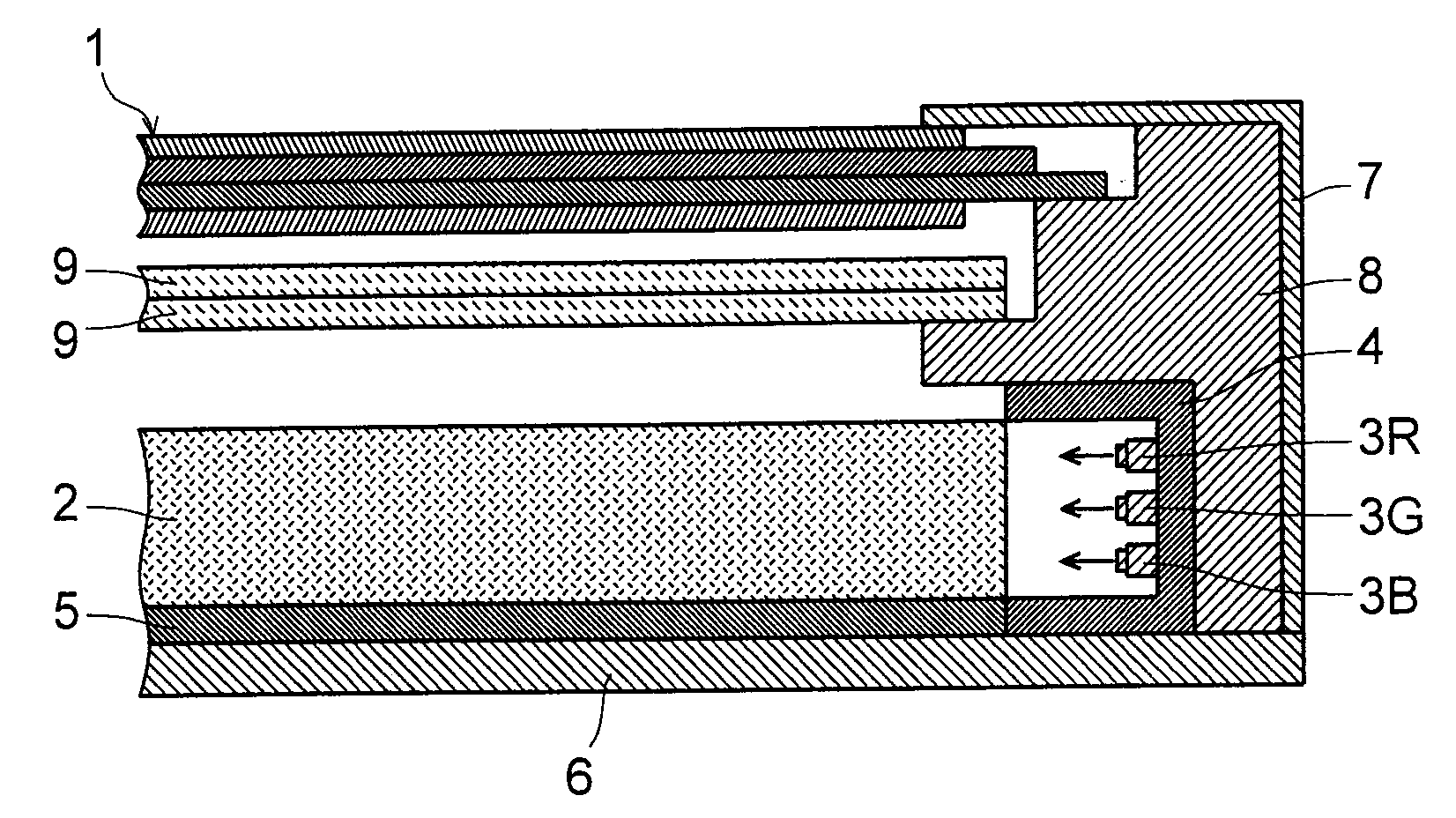
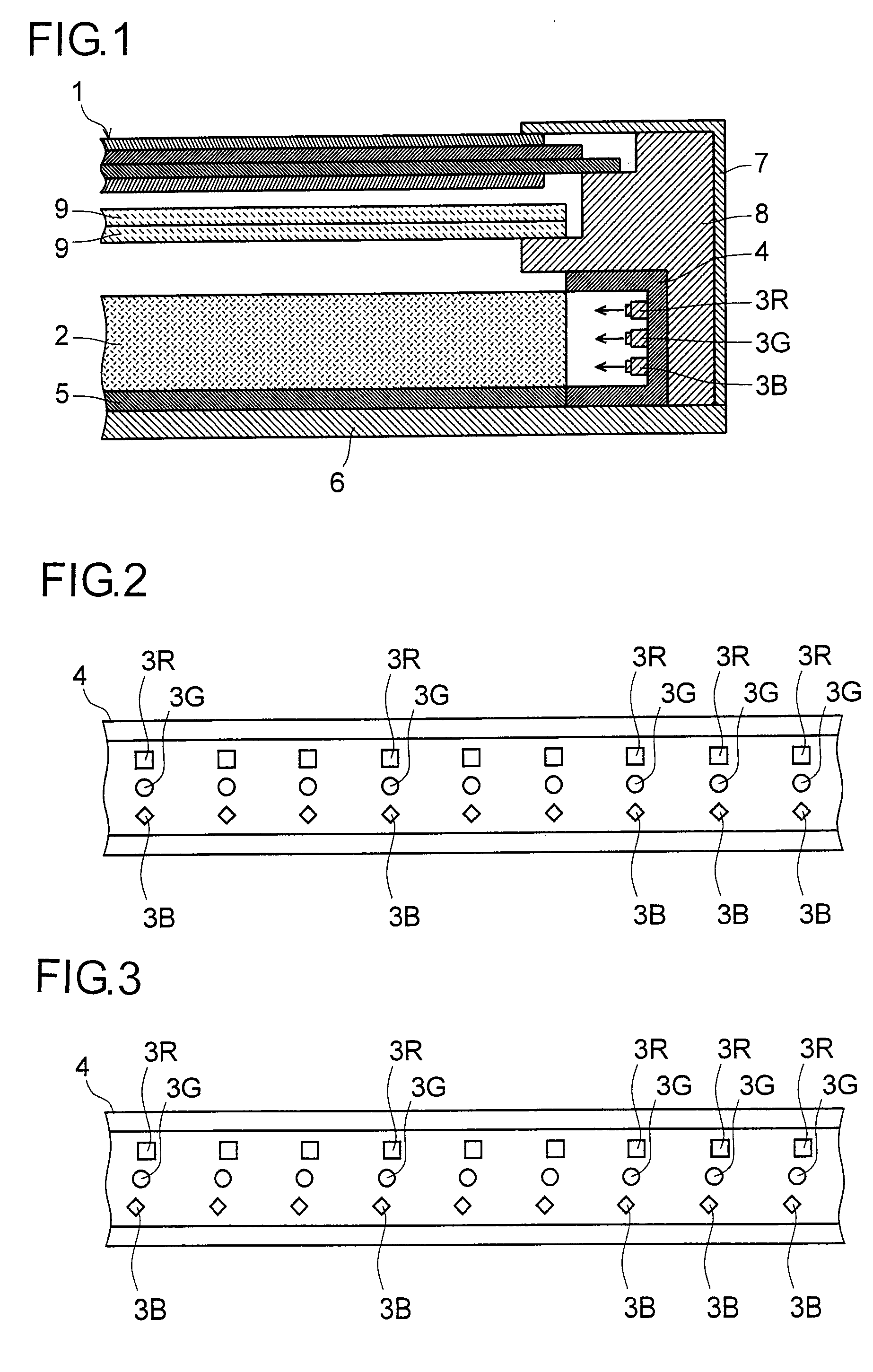
[0038]Hereinafter, preferred embodiments of the present invention will be described in detail with reference to the accompanying drawings. A description will first be given of the liquid crystal display device of a first preferred embodiment of the present invention. FIG. 1 is a cross-sectional view showing the liquid crystal display device of the first preferred embodiment; FIG. 2 is a plan view showing a light source for a backlight in the liquid crystal display device. In these figures, such parts as have the same names and functions as in FIGS. 16 to 18 are identified with common reference numerals, and the same description will not be repeated as appropriate. This also applies to second and third preferred embodiments which will be described later.

[0039]In the liquid crystal display device of this preferred embodiment, an edge-light type backlight is provided, a substantially rectangular light guide plate 2 is disposed at the back of a substantially rectangular liquid crystal d...


PUM


Abstract

A liquid crystal display device can achieve reduction in the thickness thereof and the size of its frame while reducing color unevenness even when single color LEDs are incorporated as a light source for a backlight. The liquid crystal display device includes a liquid crystal panel, a light guide plate disposed at the back of the liquid crystal panel and a light source arranged at one side of the light guide plate; the light from the light source illuminates the liquid crystal panel through the light guide plate. The light source is composed of a red, green and blue LEDs emitting red, green and blue light, respectively; the LEDs are arranged along the one side of the light guide plate, and are arranged in three rows in the direction of the thickness of the light guide plate. The colors of the light emitted from the LEDs arranged side by side in the direction of the thickness of the light guide plate are different from each other.

Description

BACKGROUND OF THE INVENTION[0001]1. Field of the Invention[0002]The present invention relates to a liquid crystal display device for use as a display screen in a thin-screen television set, a personal computer, a mobile telephone, a portable information device or the like, and more particularly to a backlight incorporated in such a liquid crystal display device.[0003]2. Description of the Related Art[0004]In general, as a backlight that illuminates, from behind, a liquid crystal panel serving as a display screen in a liquid crystal display device, one of the following two backlights is used: a so-called direct-type backlight where a light source is arranged at the back of a liquid crystal panel; and a so-called edge-light type backlight where a light source is arranged at one side (or on the opposite sides) of a frame surrounding the liquid crystal panel. As a light source for these backlights, a cold cathode fluorescent tube (CCFT) or a light emitting diode (hereinafter also called...

Claims


Application Information

Patent Timeline
Patent Type & Authority Applications(United States)
IPC IPC(8): G09G3/36
CPCG02F1/133603G02B6/0068
Inventor UEYAMA, MUNETOSHI
Owner SHARP KK
Why Eureka
Try Eureka