Light-emitting device and illuminating device

A technology for light-emitting devices and light-emitting elements, which is applied to electrical components, electric solid-state devices, circuits, etc., can solve the problems of not being able to improve the luminous efficiency of phosphors, and the luminous efficiency of light-emitting devices, so as to reduce uneven hues and suppress luminescence. Efficiency drop and joint strength enhancement effect

Inactive Publication Date: 2007-03-21
TOSHIBA LIGHTING & TECH CORP
View PDF2 Cites 19 Cited by
  • Summary
  • Abstract
  • Description
  • Claims
  • Application Information

AI Technical Summary

Problems solved by technology

Therefore, the luminous efficiency of the light-emitting device cannot be improved.
[0013] In addition, Patent Document 1 describes the use of phosphor aggregates with an average particle diameter of 3 μm to 50 μm in order to suppress uneven light emission. However, for aggregates of phosphor particles aggregated in resin, the particle diameter of the phosphor It does not increase itself, so the luminous efficiency of the phosphor depends on the particle size of the phosphor particles before aggregation, therefore, the luminous efficiency of the phosphor cannot be improved by using the aggregate of the phosphor

Method used


Image

  • Light-emitting device and illuminating device
  • Light-emitting device and illuminating device
  • Light-emitting device and illuminating device

Examples


Embodiment Construction

[0063] Hereinafter, embodiments of the present invention will be described with reference to the drawings.

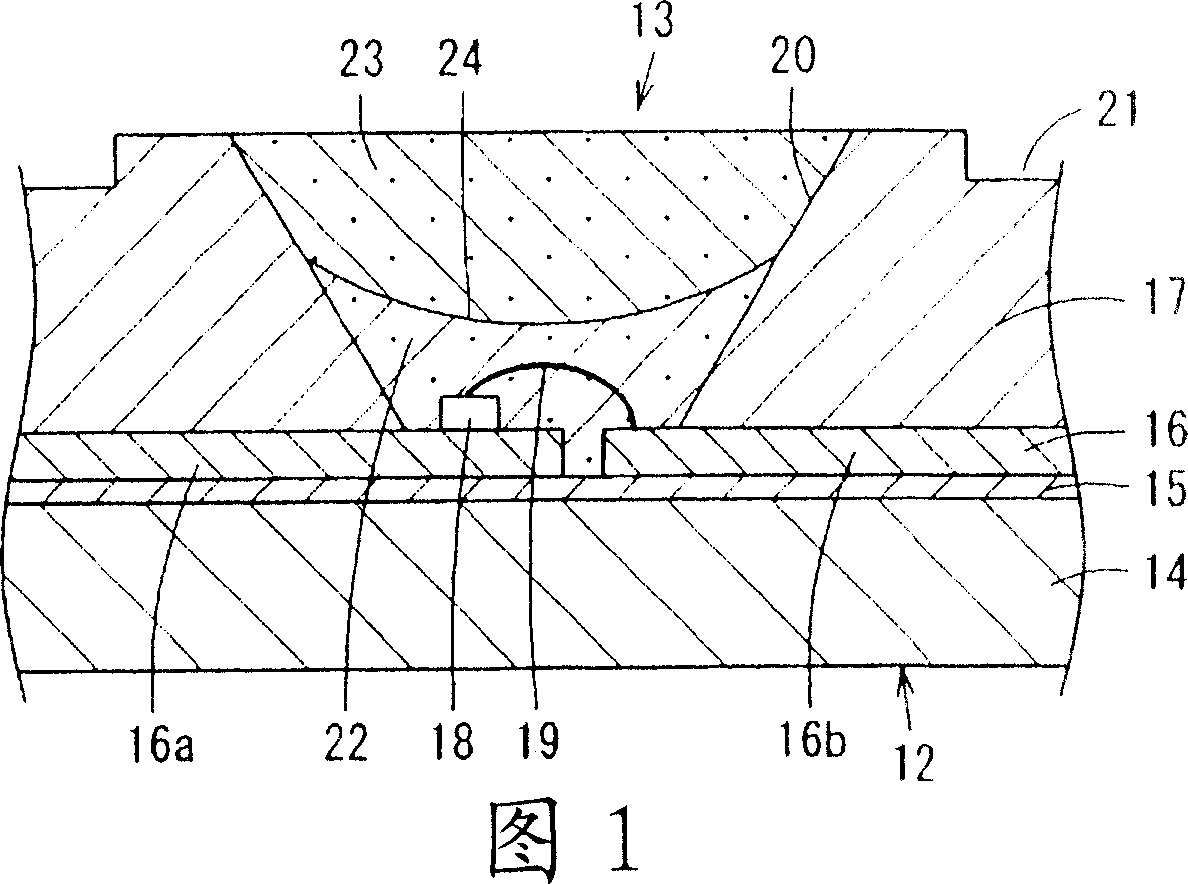
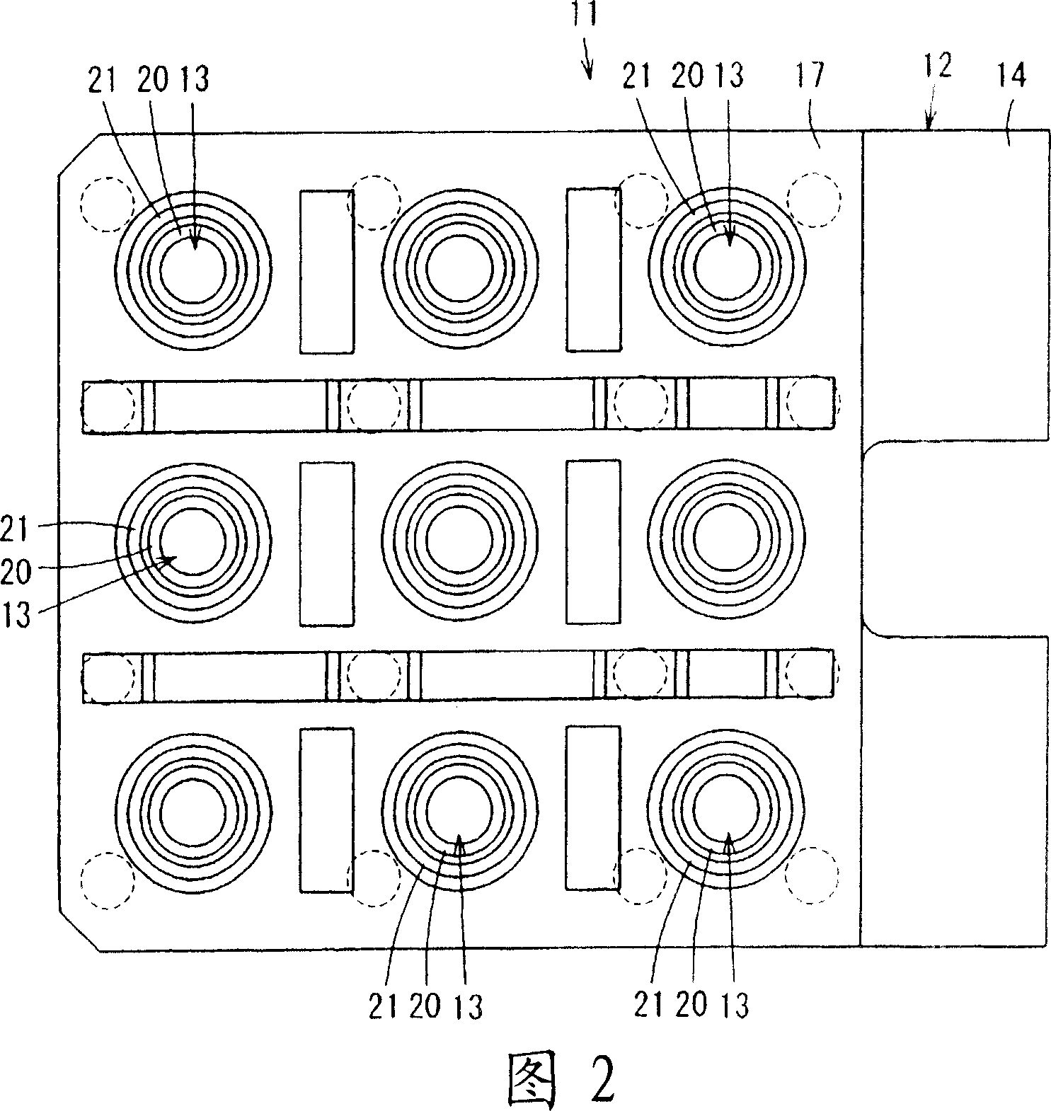
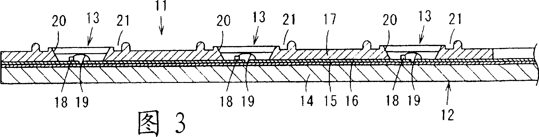
[0064] 1 to 4 show a first embodiment of the present invention. 1 is a partial enlarged cross-sectional view of a light emitting device, FIG. 2 is a top view of the light emitting device, FIG. 3 is a cross-sectional view of the light emitting device, and FIG. 4 is a table showing the relationship between the amount of scattering agent added and the light beam of the light emitting device.

[0065] As shown in FIGS. 2 and 3 , the light-emitting device 11 has a base material 12 on which a plurality of light-emitting element arrangement portions 13 are formed, for example, in a matrix of three rows and three columns.

[0066] The base material 12 has: a plate-shaped substrate 14 of aluminum (Al) or nickel (Ni), glass epoxy resin, etc. with heat dissipation and rigidity; an insulating layer 15 formed on the substrate 14; lead frame 16 ; and reflector 17 ′ formed on substra...


PUM


Abstract

Disclosed is a light-emitting device (11) wherein the luminous efficiency is improved and color variations in the emitted light are reduced. Specifically, a light-emitting diode element (18) is covered with a diffusion layer (22) wherein a diffusing agent is added to a resin. A phosphor layer (23) wherein a phosphor is added to a resin is arranged on top of the diffusion layer (22). The light from the light-emitting diode element (18) is diffused by the diffusion layer (22). By exciting the phosphor layer (23) with the light diffused at the diffusion layer and having the phosphor layer (23) emit a light, the luminous efficiency is improved and color variations in the emitted light are reduced.

Description

technical field [0001] The present invention relates to a light-emitting device using a light-emitting element as a light source, and an illuminating device with the light-emitting device. Background technique [0002] Conventionally, in a light-emitting device using a light-emitting diode element, which is a solid-state light-emitting element, as a light source, there is known a surface mount type light-emitting device in which a light-emitting diode element is disposed on a substrate and a resin is filled to cover the light-emitting diode element. device. [0003] And, in order to utilize this light-emitting device to emit white light, the following technology is known: said device mixes the blue light emitted by the blue light-emitting diode element and the yellow light emitted by the yellow light-emitting diode element (for example, refer to the patent document 1). [0004] In addition, a technique is known in which a blue light-emitting diode element is covered with a...

Claims


Application Information

Patent Timeline
Patent Type & Authority Applications(China)
IPC IPC(8): H01L33/00H01L33/58
CPCH01L2224/16225H01L2224/48091H01L2224/73265H01L2224/8592H01L2924/181
Inventor 森山严与中西晶子岩本正己野木新治小川光三清水惠一齐藤明子川岛净子三瓶友广泉昌裕户田雅宏
Owner TOSHIBA LIGHTING & TECH CORP
Why Eureka
Try Eureka