
Illumination device having multiple LED elements with varying color temperatures

a technology of led elements and led elements, applied in semiconductor devices, light source combinations, lighting and heating apparatuses, etc., can solve the problems of color unevenness particularly, color unevenness appearing prominently, and the light extraction efficiency decreases, so as to reduce color unevenness and reduce light extraction efficiency

Active Publication Date: 2010-08-12
PANASONIC INTELLECTUAL PROPERTY MANAGEMENT CO LTD
View PDF3 Cites 18 Cited by
  • Summary
  • Abstract
  • Description
  • Claims
  • Application Information

AI Technical Summary

Benefits of technology

[0014]An illumination device within the scope of the present invention is capable of reducing color unevenness without decreasing light extraction efficiency when a plurality of light-emitting devices are arranged on a substrate.
[0015]The illumination device of the present invention generally includes a light-emitting element, a plurality of light-emitting devices including a transparent enclosure such as a resin case sealing the light-emitting element, and also including a light-emitter excited by light emitted from the light-emitting element, and a substrate on which the plurality of light-emitting devices are mounted. The plurality of light-emitting devices are varied in a color temperature to reduce color unevenness.
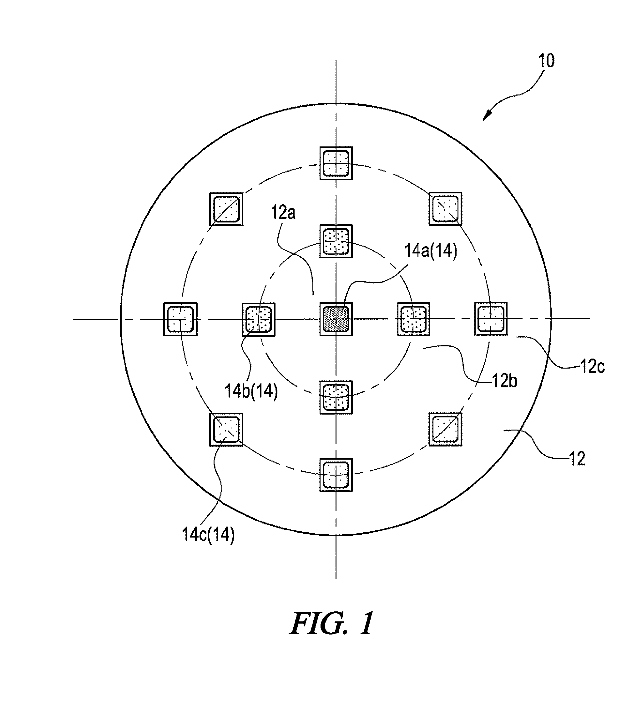
[0018]A plurality of light-emitting devices may be provided in a continuous manner. In other words, an arrangement of light-emitting devices may be provided with, for example, light-emitting devices of a first color temperature generally disposed along an inner portion of the arrangement and with light-emitting devices of a second and higher color temperature generally disposed about an outer portion of the array. Providing a plurality of the light-emitting units in a continuous manner to form the illumination device can reduce an appearance of color unevenness of the illumination device. This further has the advantage of permitting the illumination device to be formed in a wide variety of shapes such as for example a rectangle, thus widening its use.
[0019]Varying the plurality of light-emitting devices in color temperature can bring the color temperature at an outer circumferential portion closer to a color temperature at a center portion on an irradiation surface of the illumination device. Bringing the color temperature at the outer circumferential portion of the irradiation surface of the illumination device closer to the color temperature at the center portion thereof in this manner can reduce the appearance of color unevenness on the irradiation surface. This further eliminates the need for subjecting light emitted from the light-emitting devices to diffusion processing with a reflection plate or a lens. An associated decrease in light extraction efficiency may therefore be avoided.
[0020]The plurality of light-emitting devices which may be varied in color temperature in a phased manner from the center of the substrate toward the outer circumference thereof (including a condition where they are arranged with the color temperature increasing in a phased manner) may further be provided as a light-emitting unit. Consequently, an appearance of color unevenness on an irradiation surface of the light-emitting unit can be reduced.
[0021]The plurality of light-emitting devices may have a blue light-emitting diode as the light-emitting element and may further include phosphor of a white type including a yellow color. When the phosphor is of a white type, the color unevenness is generally likely to appear in the illumination device. Thus, varying the plurality of light-emitting devices in the color temperature in a phased manner from the center of the substrate toward the outer circumference thereof (including a condition where they are arranged with the color temperature increasing in a phased manner) can desirably reduce an appearance of color unevenness in the illumination device.

Problems solved by technology

Problems of color unevenness particularly arise in the event where a proximity position is irradiated by an illumination device provided with a white LED.
It may further be assumed that when a reflection plate or a lens is used for obtaining high illumination intensity, or when an LED (for example, an LED package loaded with a plurality of LED elements) with a large light-emitting portion is used, a problematic appearance of color unevenness becomes prominent.
However, this has led to a decrease in light extraction efficiency.
Moreover, using a reflection plate or a lens subjected to diffusion processing in the LED with a large light-emitting portion requires a very large lens or a reflection plate, thus resulting in failure to achieve a compact illumination device.

Method used


Image

  • Illumination device having multiple LED elements with varying color temperatures
  • Illumination device having multiple LED elements with varying color temperatures
  • Illumination device having multiple LED elements with varying color temperatures

Examples


Embodiment Construction

[0030]Throughout the specification and claims, the following terms take at least the meanings explicitly associated herein, unless the context dictates otherwise. The meanings identified below do not necessarily limit the terms, but merely provide illustrative examples for the terms. The meaning of “a,”“an,” and “the” may include plural references, and the meaning of “in” may include “in” and “on.” The phrase “in one embodiment,” as used herein does not necessarily refer to the same embodiment, although it may.

[0031]Hereinafter, preferred embodiments of the present invention may be described with reference to the accompanying drawings.

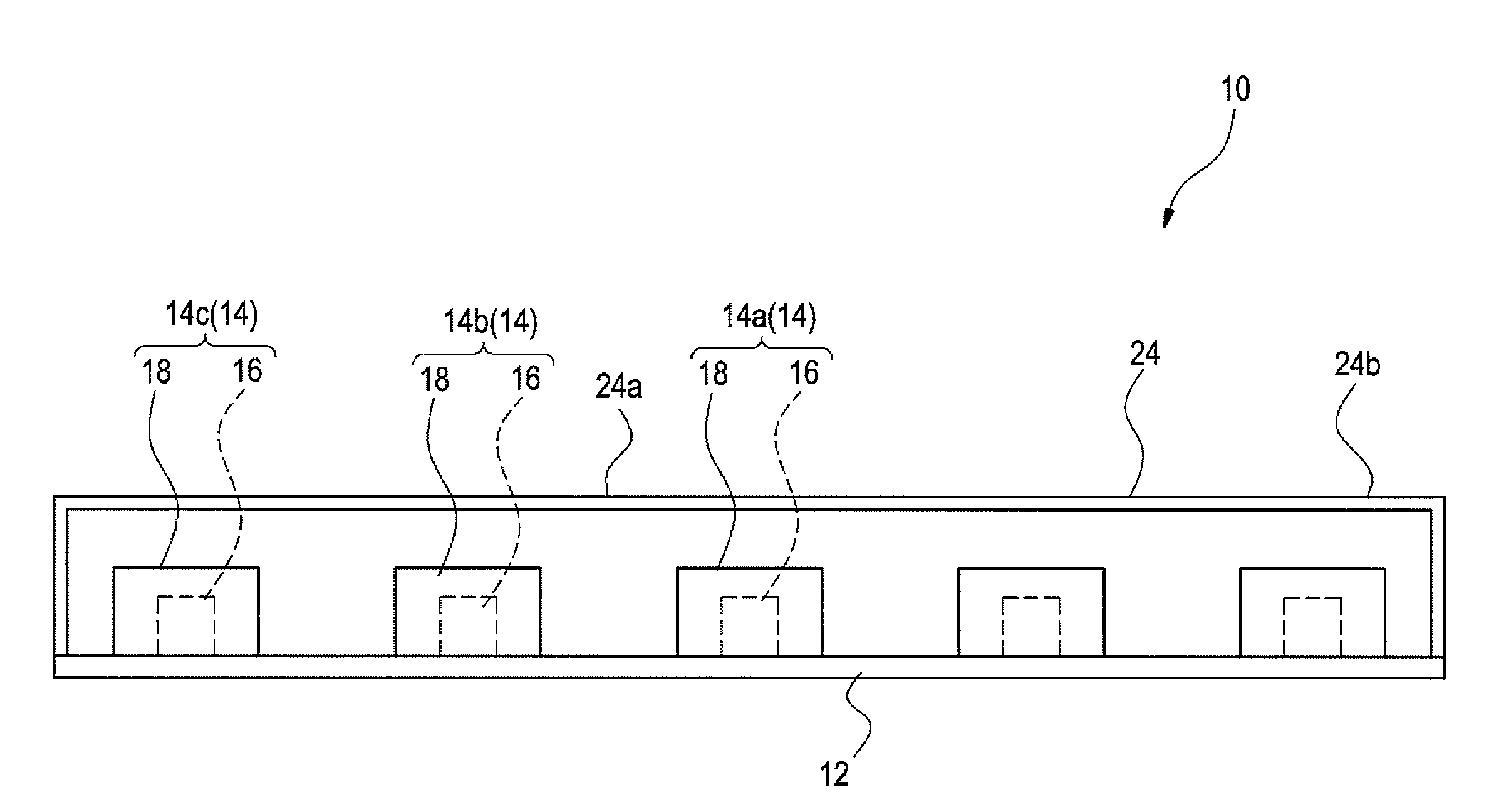
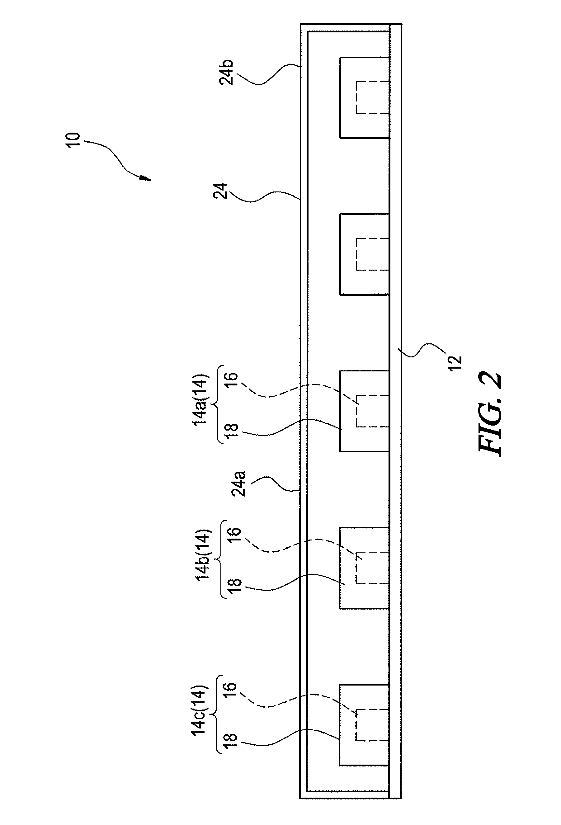
[0032]Referring to FIG. 1, in an embodiment an illumination device 10 is provided with a substrate 12 formed into a disc-like shape and a plurality of light-emitting devices 14 mounted on the substrate 12.

[0033]The substrate 12 as shown is a component on which the plurality of light-emitting devices 14 are mounted concentrically at predetermined interv...


PUM


Abstract

An illumination device is provided with an arrangement for reducing color unevenness. A plurality of light-emitting devices are provided, each of which includes a transparent enclosure sealing a light-emitting element and further including a phosphor excited by light emitted from the light-emitting element. A substrate is provided upon which the plurality of light-emitting devices are mounted. The light-emitting devices are provided with predetermined color temperatures that vary in accordance with their position along the substrate to reduce color unevenness, for example increasing in a phased manner from the center of the substrate toward the outer circumference thereof.

Description

[0001]A portion of the disclosure of this patent document contains material that is subject to copyright protection. The copyright owner has no objection to the reproduction of the patent document or the patent disclosure, as it appears in the U.S. Patent and Trademark Office patent file or records, but otherwise reserves all copyright rights whatsoever.CROSS-REFERENCES TO RELATED APPLICATIONS[0002]This application claims benefit of the following patent application(s) which is / are hereby incorporated by reference: Japan Patent Application No. 2009-003768, filed Jan. 9, 2009.STATEMENT REGARDING FEDERALLY SPONSORED RESEARCH OR DEVELOPMENT[0003]Not ApplicableREFERENCE TO SEQUENCE LISTING OR COMPUTER PROGRAM LISTING APPENDIX[0004]Not ApplicableBACKGROUND OF THE INVENTION[0005]The present invention relates to illumination devices. More particularly, the present invention relates to illumination devices provided with a plurality of light-emitting devices which includes in a resin case a l...

Claims


Application Information

Patent Timeline
Patent Type & Authority Applications(United States)
IPC IPC(8): H01L33/00
CPCF21K9/00F21Y2113/005F21Y2105/003F21Y2101/02F21Y2105/10F21Y2105/12F21Y2113/13F21Y2115/10
Inventor TAKASHIMA, JUN
Owner PANASONIC INTELLECTUAL PROPERTY MANAGEMENT CO LTD
Learn More