
Electrostatic air cleaning device

an electrostatic air cleaning and air cleaning technology, applied in the direction of variable capacitors, colloidal chemistry, instruments, etc., can solve the problems of limited air electrical dielectric strength, general failure to consider the movement of charged particulates and their trajectory or path being charged, and relative poor collecting efficiency of electrostatic devices, etc., to achieve the effect of increasing the thickness of the electrode, avoiding airflow disturbance, and minimizing and/or avoiding disturbance of airflow

Inactive Publication Date: 2006-12-19
KRONOS ADVANCED TECH
View PDF205 Cites 56 Cited by
  • Summary
  • Abstract
  • Description
  • Claims
  • Application Information

AI Technical Summary

Benefits of technology

"The patent text describes an improvement to electrostatic devices used for air cleaning. The invention involves adding rounded bulges to the electrodes, which decrease the electric field around the edges of the device. This results in a higher potential difference between the electrodes without causing arcing or sparking. The bulges also help to create a low velocity zone that helps to trap particles and keep them on the collecting electrodes. Overall, the invention improves the efficiency of the device by increasing the movement of charged particles and minimizing the impact of air flow."

Problems solved by technology

One cause for the relatively poor collecting efficiency of electrostatic devices is a general failure to consider movement of the charged particulates and their trajectory or path being charged in the area of the corona discharge.
However, a maximum electric field potential difference is limited by the air electrical dielectric strength, i.e., the breakdown voltage of the fluid whereupon arcing will occur.
If the potential difference exceeds some threshold level then an electrical breakdown of the dielectric occurs, resulting in extinguishment of the field and interruption of the air cleaning processing / operations.

Method used


Image

  • Electrostatic air cleaning device
  • Electrostatic air cleaning device
  • Electrostatic air cleaning device

Examples


Embodiment Construction

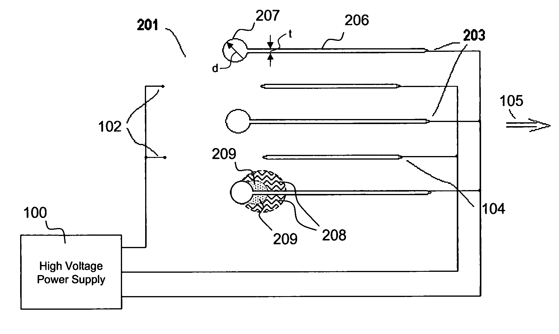
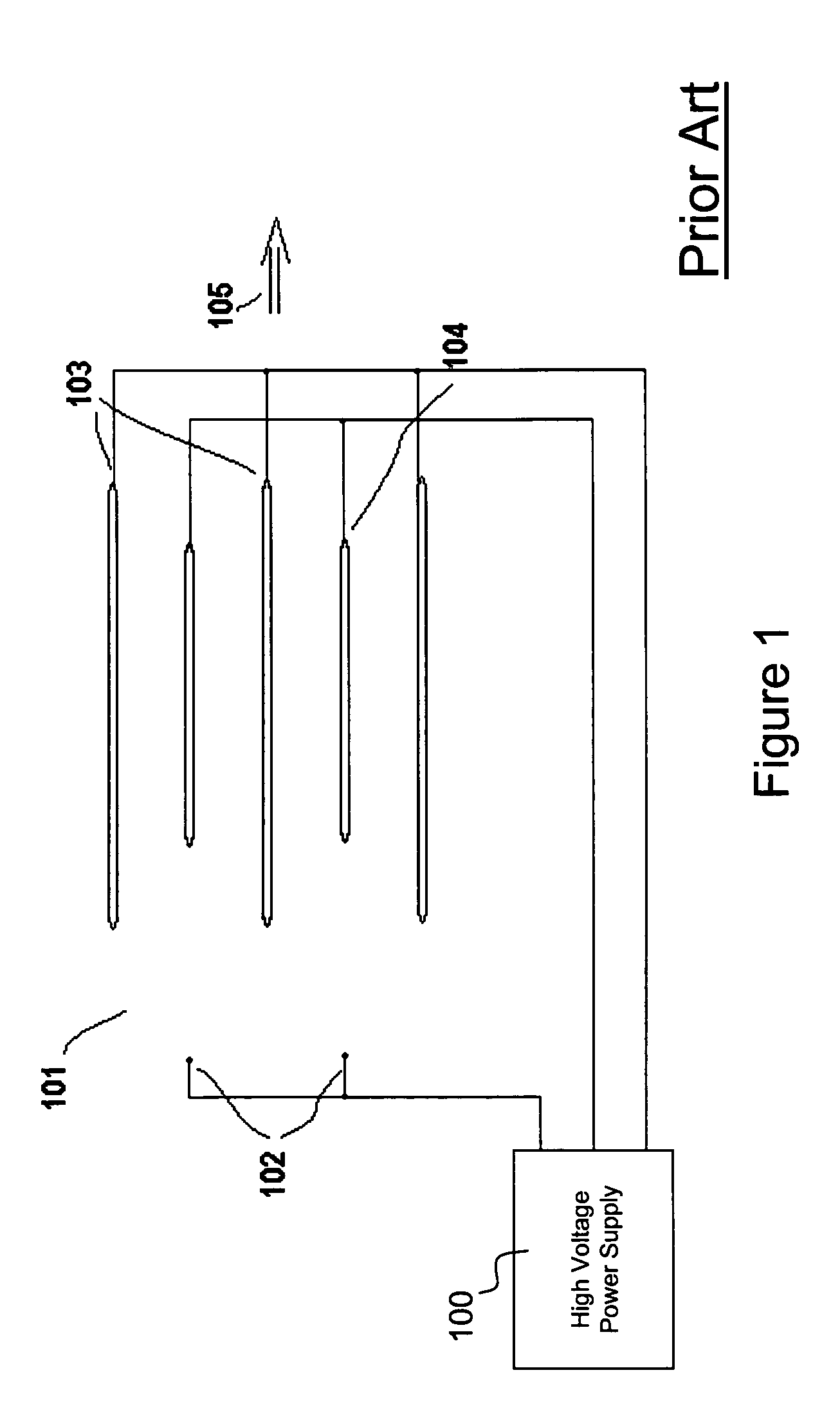
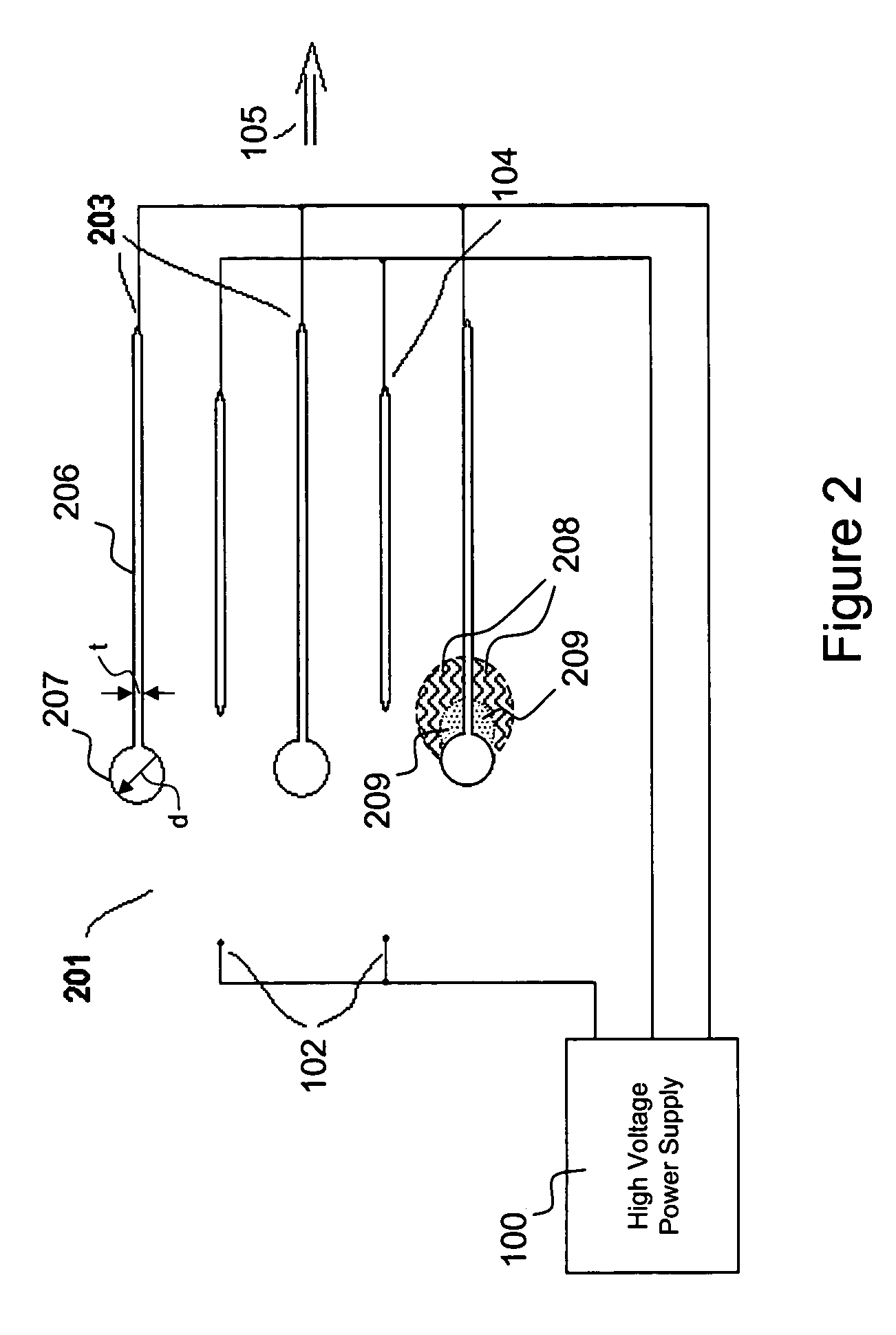
[0038]FIG. 1 is a schematic drawing of an array of electrodes that are part of an electrostatic air cleaning device according to the prior art. As shown, an electrostatic air cleaning device includes a high voltage power supply 100 connected to an array of electrodes 101 through which a fluid, such as air, is propelled by the action of the electrostatic fields generated by the electrodes, i.e., the corona discharge created by corona electrodes 102 accelerating air toward oppositely charged complementary electrodes such as collecting electrodes 103. The electrodes are connected to a suitable source of a high voltage (e.g., high voltage power supply 100), in the 10 kV to 25 kV range for typical spacing of the electrodes.

[0039]The array of electrodes includes three groups: (i) a subarray of laterally spaced, wire-like corona electrodes 102 (two are shown) which array is longitudinally spaced from (ii) a subarray of laterally spaced, plate-like collecting electrodes 103 (three are shown...


PUM


Abstract

An electrostatic air cleaning device includes an array of electrodes. The electrodes include corona electrodes connected to a suitable source of high voltage so as to generate a corona discharge. Laterally displaced collecting electrodes include one or more bulges that have aerodynamic frontal “upwind” surfaces and airflow disrupting tailing edges downwind that create quite zones for the collection of particulates removed from the air. The bulges may be formed as rounded leading edges on the collecting electrodes and / or as ramped surfaces located, for example, along a midsection of the electrodes. Repelling electrodes positioned between pairs of the collecting electrodes may include similar bulges such as cylindrical or semi-cylindrical leading and / or trailing edges.

Description

RELATED APPLICATIONS[0001]The instant application is related to U.S. patent application Ser. No. 09 / 419,720 filed Oct. 14, 1999 and entitled Electrostatic Fluid Accelerator, now U.S. Pat. No. 6,504,308; U.S. patent application Ser. No. 10 / 187,983 filed Jul. 3, 2002 and entitled Spark Management And Device; U.S. patent application Ser. No. 10 / 175,947 filed Jun. 21, 2002 and entitled Method Of And Apparatus For Electrostatic Fluid Acceleration Control Of A Fluid Flow and the Continuation-In-Part thereof, U.S. patent application Ser. No. 10 / 735,302 filed Dec. 15, 2003 of the same title; U.S. patent application Ser. No. 10 / 188,069 filed Jul. 3, 2002 and entitled Electrostatic Fluid Accelerator For And A Method Of Controlling Fluid Flow; U.S. patent application Ser. No. 10 / 352,193 filed Jan. 28, 2003 and entitled An Electroststic Fluid Accelerator For Controlling Fluid Flow; U.S. patent application Ser. No. 10 / 295,869 filed Nov. 18, 2002 and entitled Electrostatic Fluid Accelerator; U.S....

Claims


Application Information

Patent Timeline
Patent Type & Authority Patents(United States)
IPC IPC(8): B03C3/08B03C3/12B03C3/47
CPCB03C3/08B03C3/47Y10S55/39
Inventor KRICHTAFOVITCH, IGOR A.GOROBETS, VLADIMIR L.
Owner KRONOS ADVANCED TECH
Learn More