Ignition device for a laser ignition of an internal combustion engine

a laser ignition and internal combustion engine technology, applied in combustion engines, machines/engines, gas turbine plants, etc., can solve the problems of clear pressure rise in the intervening space, stressing the sealing surface between the combustion chamber window and the inner sleeve of the housing, etc., to improve the service life and reliability

Inactive Publication Date: 2011-08-25
ROBERT BOSCH GMBH
View PDF4 Cites 7 Cited by
  • Summary
  • Abstract
  • Description
  • Claims
  • Application Information

AI Technical Summary

Benefits of technology

[0008]An object of the present invention is providing an ignition laser having an additionally improved service life and reliability.

Problems solved by technology

For if, during operation of the laser ignition device, only minimal leakages should occur, this may lead to the pressure in the intervening space rising clearly above the environmental pressure, and as a result greatly stressing the sealing surface between the combustion chamber window and the inner sleeve of the housing.

Method used


Image

  • Ignition device for a laser ignition of an internal combustion engine
  • Ignition device for a laser ignition of an internal combustion engine
  • Ignition device for a laser ignition of an internal combustion engine

Examples


Embodiment Construction

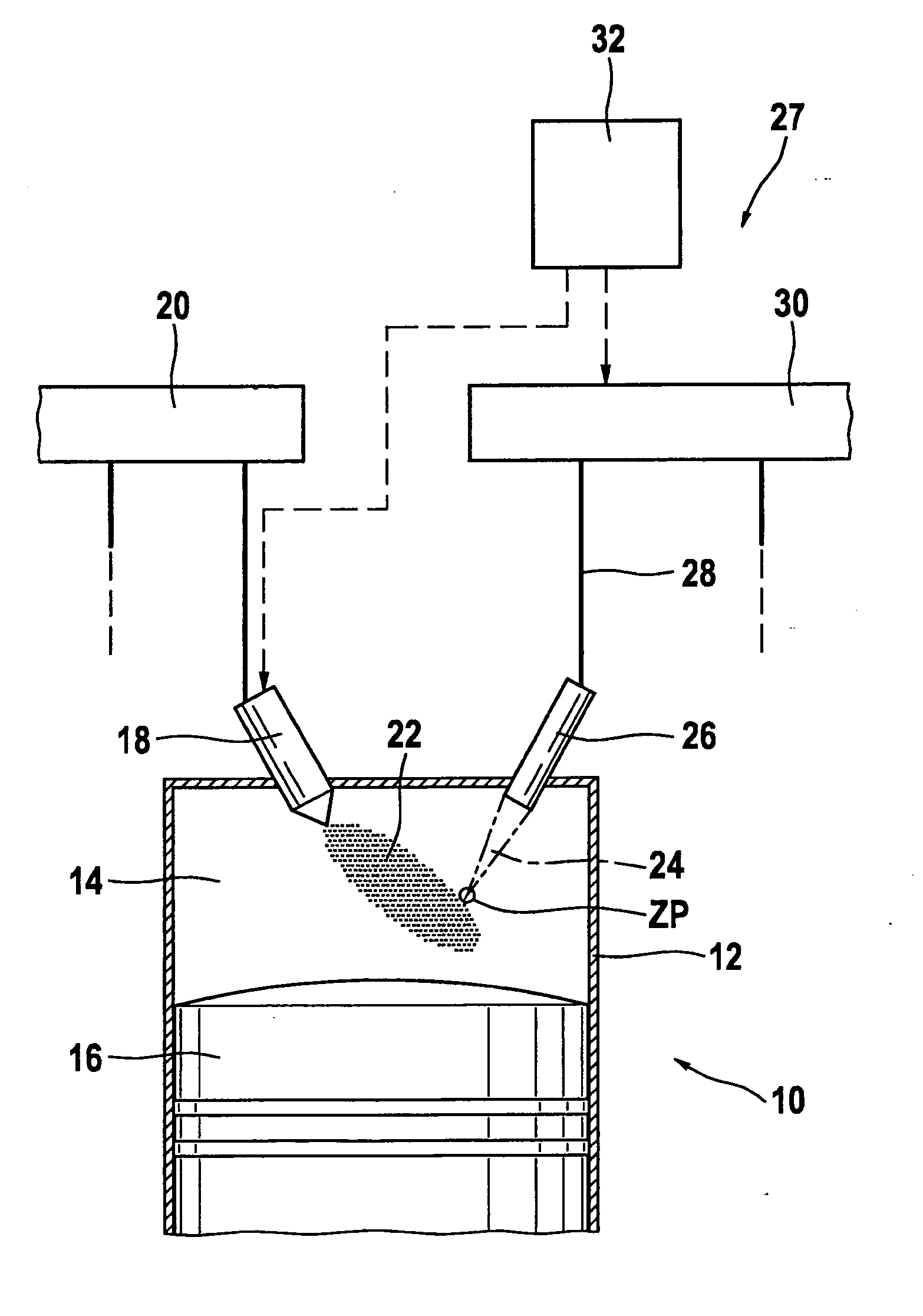
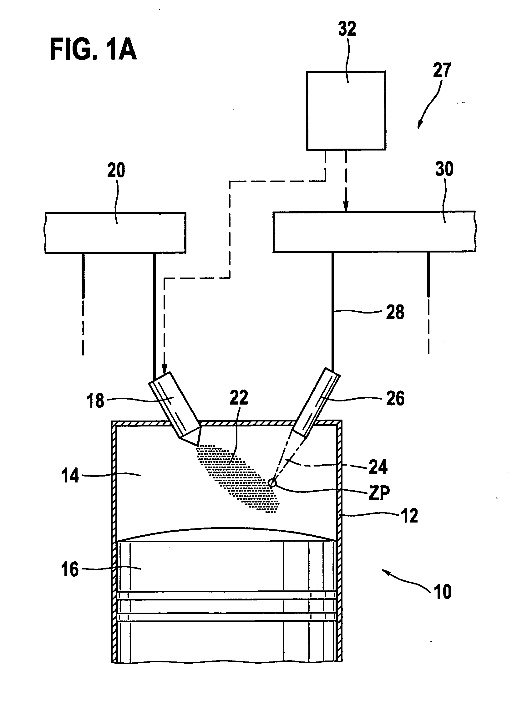
[0022]In FIG. 1a, the entire internal combustion engine is denoted by reference numeral 10. It may be used for driving a motor vehicle that is not shown. Internal combustion engine 10 usually includes multiple cylinders, only one of which is designated in FIG. 1 by reference numeral 12. A combustion chamber 14 of cylinder 12 is bounded by a piston 16. Fuel reaches combustion chamber 14 directly through an injector 18, which is connected to a fuel pressure reservoir 20 that is also designated as a rail. Alternatively the fuel-air mixture may also be formed outside of combustion chamber 14, for instance, in the intake manifold.

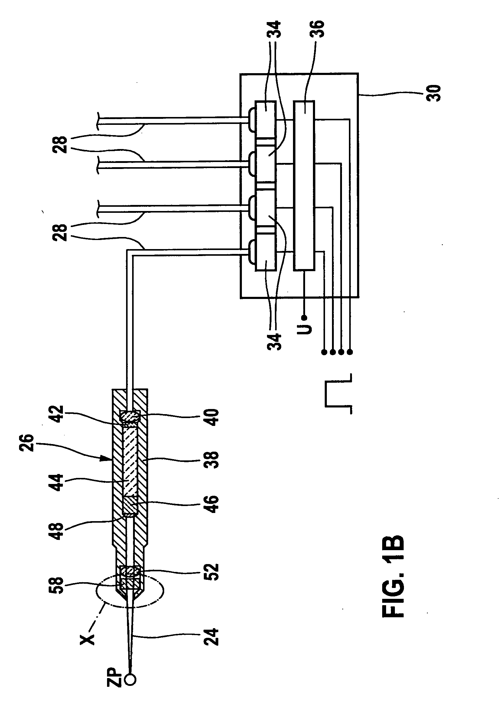
[0023]Fuel-air mixture 22 inside combustion chamber 14 is ignited by a laser pulse 24, which is radiated into combustion chamber 14 by an ignition device 27 which includes an ignition laser 26. For this purpose, laser device 24 is fed, via a light-guide device 28, with a pumping light provided by a pumping light source 30. Pumping light source 30 is controlled b...


PUM


Abstract

An ignition laser is provided for an internal combustion engine, in which the combustion chamber window is connected to a housing of the ignition laser in a gas-resistant, pressure-resistant, and temperature-resistant manner. Furthermore, a pressure relief bore is present which effectively prevents a pressure increase in the housing of the ignition laser.

Description

BACKGROUND OF THE INVENTION[0001]1. Field of the Invention[0002]The present invention relates to an ignition device for providing laser ignition of an internal combustion engine.[0003]2. Description of Related Art[0004]A so-called laser ignition is known from published international PCT patent application WO 2005 / 066488 A1. This laser ignition includes an ignition laser, which extends into the combustion chamber of an internal combustion engine. The ignition laser is optically pumped by a pumping light source via a fiber optic guide.[0005]At one end of the ignition laser facing the combustion chamber, there is a so-called combustion chamber window, which is able to transmit the laser beams generated for the ignition laser. This combustion chamber window has to be accommodated in a sealing manner in a housing of the ignition laser. There are high requirements on the sealing between the combustion chamber window and the housing, because during the operation of the internal combustion ...

Claims


Application Information

Patent Timeline
Patent Type & Authority Applications(United States)
IPC IPC(8): F02P23/04
CPCF02P23/04F02C7/264
Inventor WEINROTTER, MARTINWOERNER, PASCALRAIMANN, JUERGENWOLZ, DIETER
Owner ROBERT BOSCH GMBH
Why Eureka
Try Eureka