Dynamic user interface elements

a user interface and element technology, applied in the field of dynamic user interface elements, can solve the problem that the usefulness of the display of ui elements is limited to various users, and achieve the effect of reducing the number of users

Active Publication Date: 2011-09-01
ADOBE SYST INC
View PDF3 Cites 48 Cited by
  • Summary
  • Abstract
  • Description
  • Claims
  • Application Information

AI Technical Summary

Problems solved by technology

In typical applications, displays of UI elements are limited in their usefulness to various users.

Method used


Image

  • Dynamic user interface elements
  • Dynamic user interface elements
  • Dynamic user interface elements

Examples


Embodiment Construction

[0013]The invention can be implemented in numerous ways, including as a process, an apparatus, a system, a composition of matter, a computer readable medium such as a computer readable storage medium or a computer network wherein program instructions are sent over optical or communication links. In this specification, these implementations, or any other form that the invention may take, may be referred to as techniques. A component such as a processor or a memory described as being configured to perform a task includes both a general component that is temporarily configured to perform the task at a given time or a specific component that is manufactured to perform the task. In general, the order of the steps of disclosed processes may be altered within the scope of the invention.

[0014]A detailed description of one or more embodiments of the invention is provided below along with accompanying figures that illustrate the principles of the invention. The invention is described in conne...


PUM


Abstract

A set of rules and a current context for a user is obtained. The set of rules and the current context are used to determine a rule weight for each of a set of user interface elements. One or more of the user interface elements is caused to be displayed. Which user interface elements are displayed is based at least in part on the rule weights.

Description

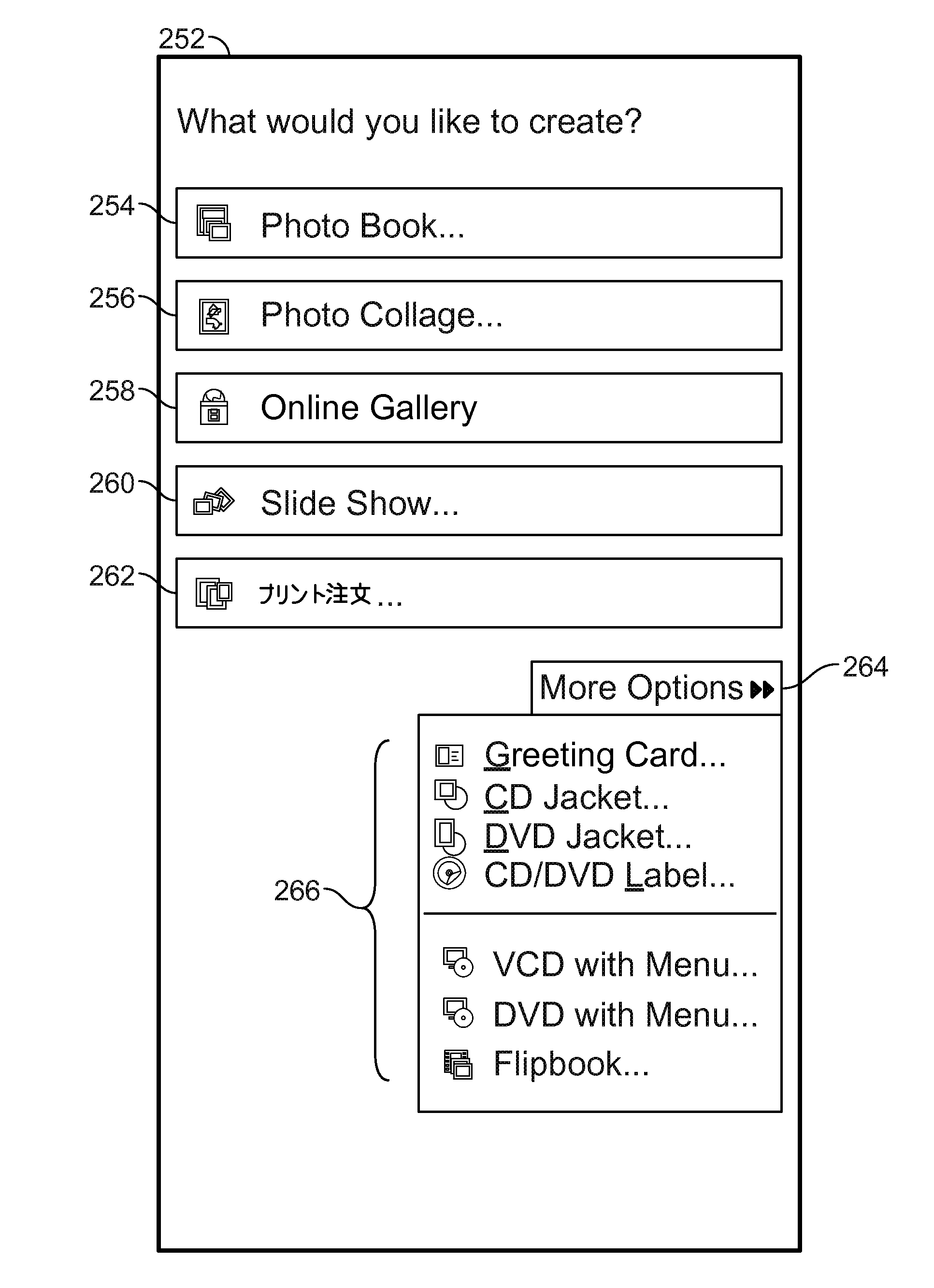
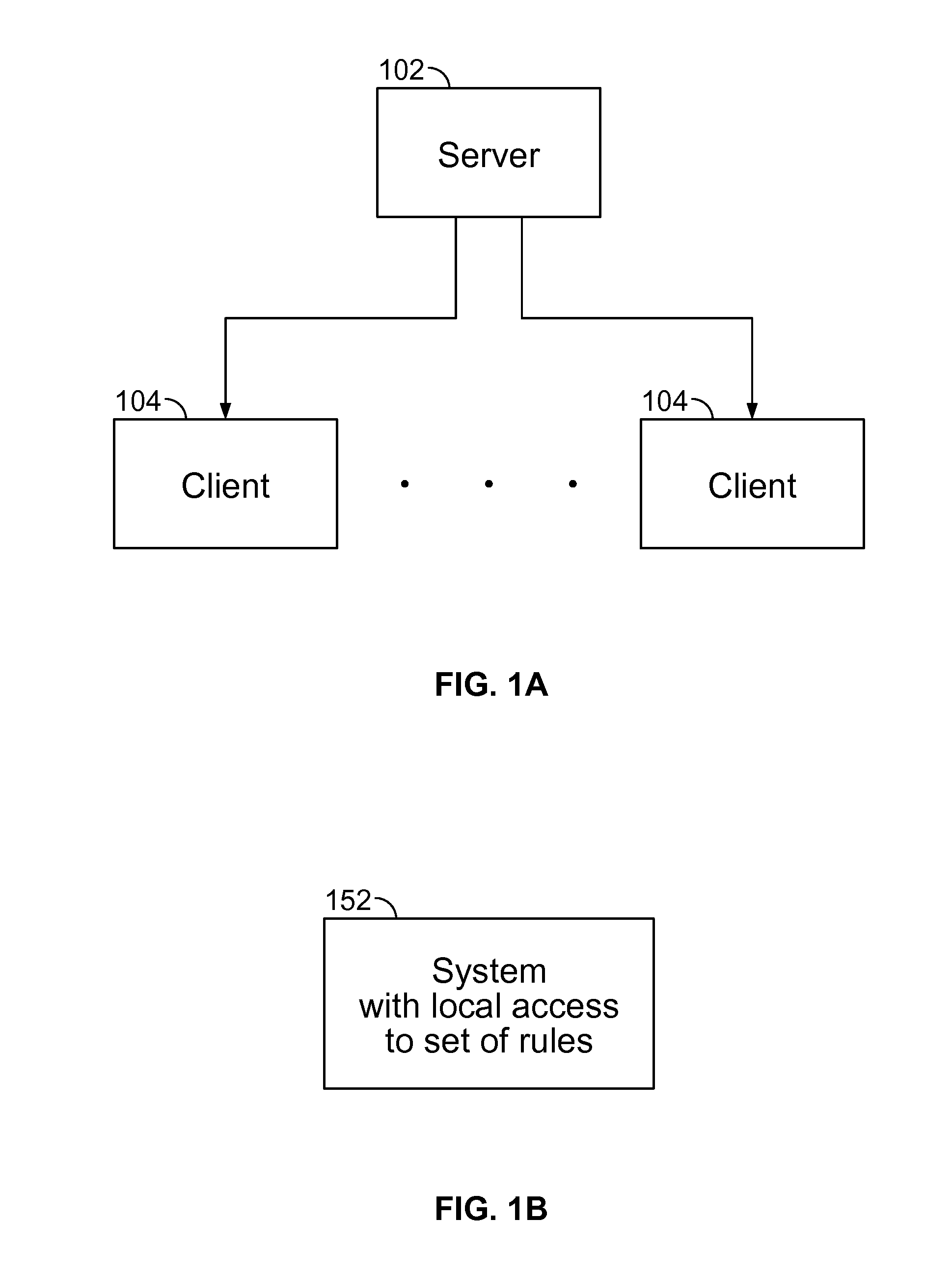
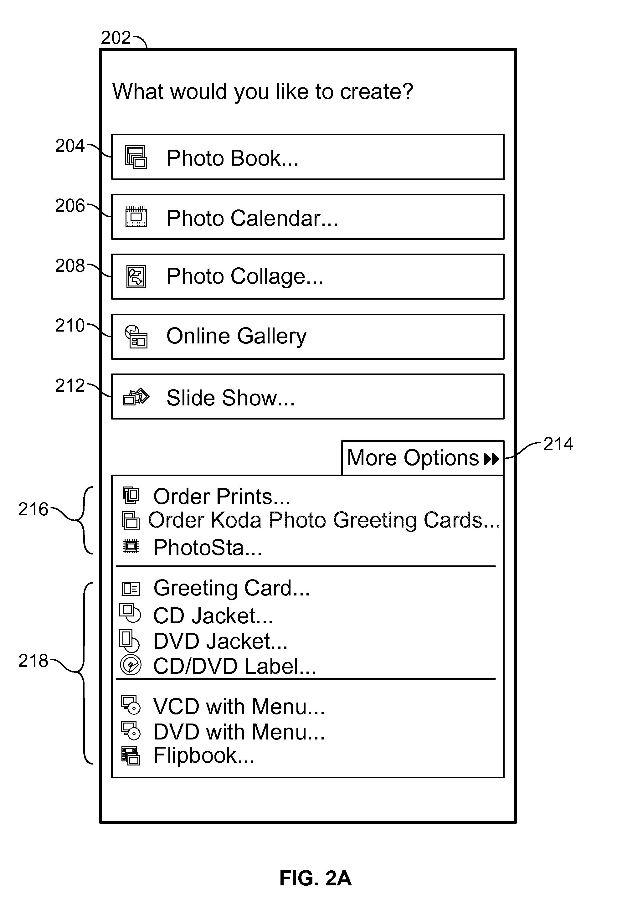
CROSS REFERENCE TO OTHER APPLICATIONS[0001]This application is a continuation of co-pending U.S. patent application Ser. No. 11 / 903,467, entitled DYNAMIC USER INTERFACE ELEMENTS filed Sep. 21, 2007 which is incorporated herein by reference for all purposes.BACKGROUND OF THE INVENTION[0002]In computer applications, a list of user interface (UI) elements accomplishing various functionality are often shown at the same place, for example the same window, menu, frame, tab, or pane. In typical applications, displays of UI elements are limited in their usefulness to various users. Therefore, improvements in the display of UI elements would be useful.BRIEF DESCRIPTION OF THE DRAWINGS[0003]Various embodiments of the invention are disclosed in the following detailed description and the accompanying drawings.[0004]FIG. 1A is a block diagram illustrating an embodiment of a system for ranking UI elements in a dynamic manner.[0005]FIG. 1B is a block diagram illustrating an embodiment of a system ...

Claims


Application Information

Patent Timeline
Patent Type & Authority Applications(United States)
IPC IPC(8): G06F3/048
CPCG06F9/451
Inventor SINGH, DURGA DEEPTHI RAMESHRANGANATHAN, SREEDHARMYROLD, JAMIE
Owner ADOBE SYST INC
Why Eureka
Try Eureka