Low Profile Ring Box with Sliding Lid and Pivoting Ring Holder

a ring box and low-profile technology, applied in the field of low-profile ring boxes with sliding lids and pivoting ring holders, can solve the problems of clunky ring boxes that are too large and clunky to conceal in pants or coat pockets without being noticed

a ring box and low-profile technology, applied in the field of low-profile ring boxes with sliding lids and pivoting ring holders, can solve the problems of clunky ring boxes that are too large and clunky to conceal in pants or coat pockets without being noticed

US20110240492A1Inactive Publication Date: 2011-10-06HINSON MATTHEW CALVIN +1

Image

  • Low Profile Ring Box with Sliding Lid and Pivoting Ring Holder
  • Low Profile Ring Box with Sliding Lid and Pivoting Ring Holder
  • Low Profile Ring Box with Sliding Lid and Pivoting Ring Holder

Examples


Embodiment Construction

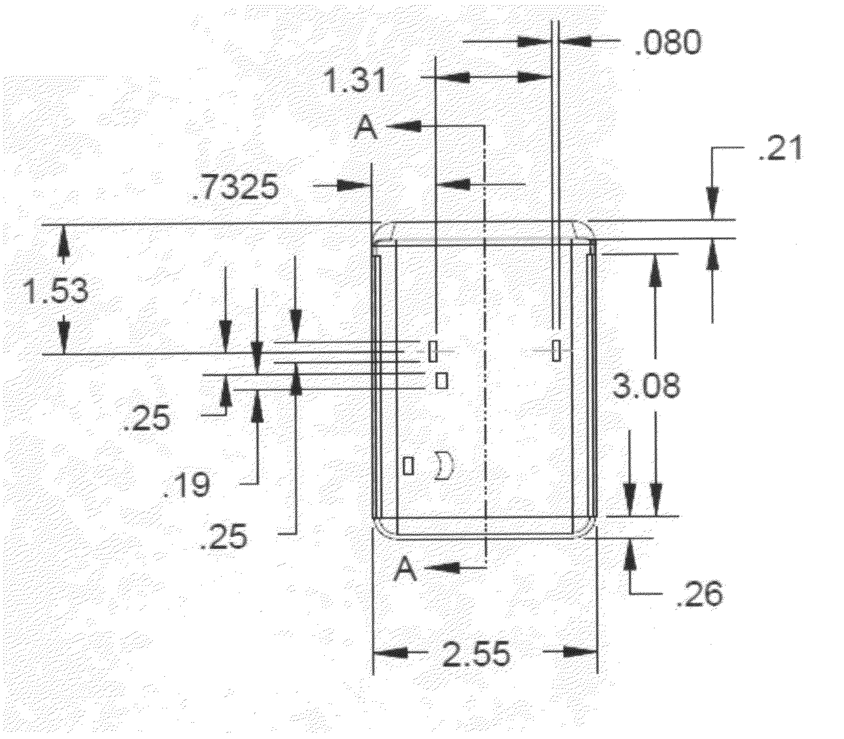
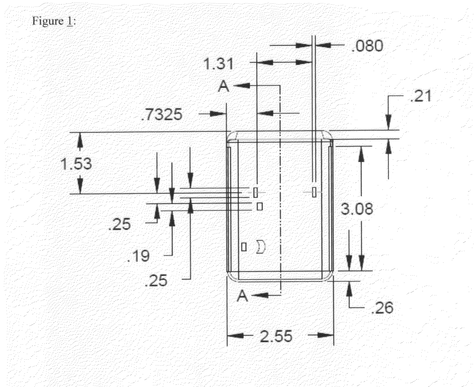
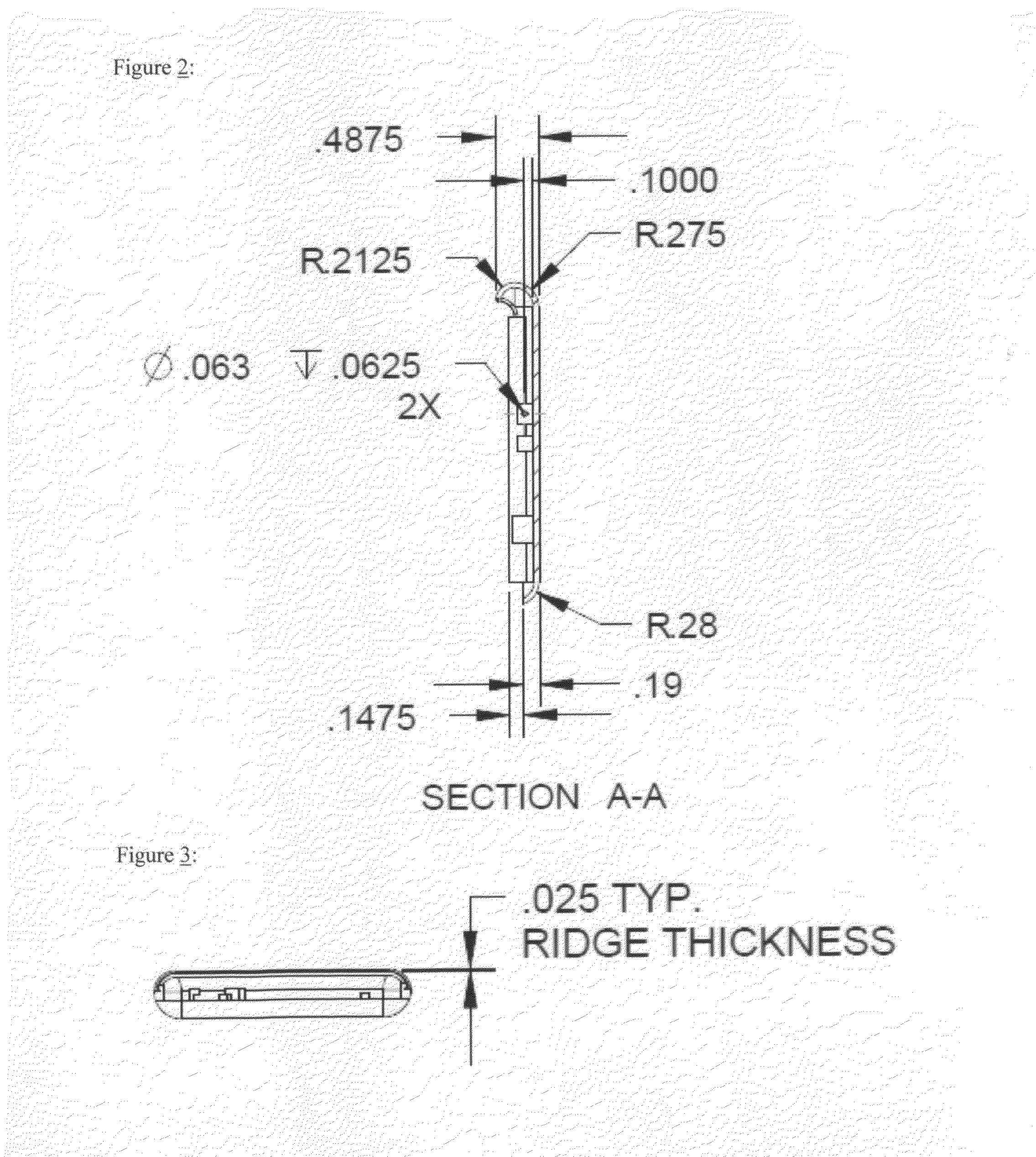
[0020]The Low Profile Ring Box with Sliding Lid and Pivoting Ring Holder is designed to be easily and discreetly stored in a coat or pant pocket for the purpose of the presentation of an engagement ring. It can also be used as a ring storage device that easily fits in a purse or hand bag. The assembly has four major parts: the base housing, the sliding lid, the pivoting ring holder, and the pull tab. The base housing has rails that interlock with the sliding lid and act as a guide upon which the sliding lid will slide. The base housing also has two blocks adjacent to each other that have holes in them. These blocks accept the axle pin that holds the pivoting ring holder in place. It is about this axle pin that the pivoting ring holder pivots. The pivoting ring holder pivots when it is pulled back by the pull tab which attaches to the pivoting ring holder via two studs that fit into two holes opposite one another at the back of the pivoting ring holder. The pull tab has a slot in it ...


PUM


Abstract

The invention is a ring box with a low profile, a sliding lid, and a pivoting ring holder. The sliding lid and pivoting ring holder allow the ring box to have a low profile. An engagement ring or any other type of ring can be placed in the pivoting ring holder and temporarily be stored discreetly in a pant or jacket pocket until it is presented, at which time the lid is pulled back, the ring in the pivoting ring holder is pivoted from a horizontal position to a vertical position, and three LEDs are lit up, shining on the ring being presented.

Description

CROSS-REFERENCE TO RELATED APPLICATIONS[0001]Not ApplicableSTATEMENT REGARDING FEDERALLY SPONSORED RESEARCH OR DEVELOPMENT[0002]Not ApplicableREFERENCE TO SEQUENCE LIST, A TABLE, OR A COMPUTER PROGRAM LISTING COMPACT DISC APPENDIX[0003]Not ApplicableBACKGROUND OF THE INVENTION[0004]In a typical marriage proposal, a man buys an engagement ring and surprises his hopeful bride-to-be, presenting it to her by opening a ring box while down on one knee. The trick is to conceal the ring until the time and place of the presentation. The problem is that almost all ring boxes are too large and clunky to conceal in a pant or coat pocket without being noticed. This problem is addressed with the invention of the Low Profile Ring Box with Sliding Lid and Pivoting Ring Holder.BRIEF SUMMARY OF THE INVENTION[0005]The Low Profile Ring Box with Sliding Lid and Pivoting Ring Holder is a new type of ring box both for presentation and storage usage. It is pocket-sized and low profile with a depth of aroun...

Claims


Application Information

Patent Timeline
06 Oct 2011
Publication
US20110240492A1
IPC
A45C11/16
CPC
A45C11/16
Inventors
HINSON, MATTHEW CALVIN; ANDREWS, MARK ROSS