Patient positioning system and rail for use therein
a positioning system and patient technology, applied in the direction of elevated railways, transportation and packaging, ways, etc., can solve the problems of difficult movement for sick and/or disabled persons from one position
- Summary
- Abstract
- Description
- Claims
- Application Information
AI Technical Summary
Problems solved by technology
Method used
Image

Examples
first embodiment
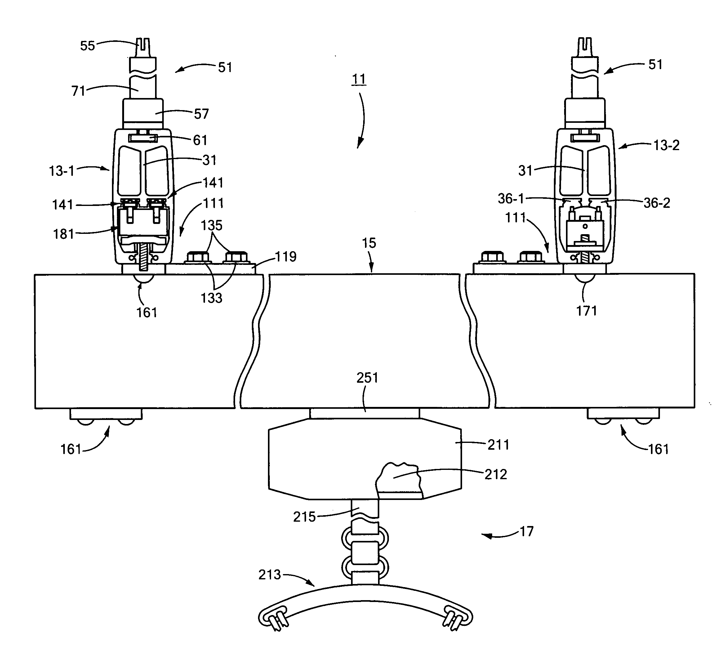
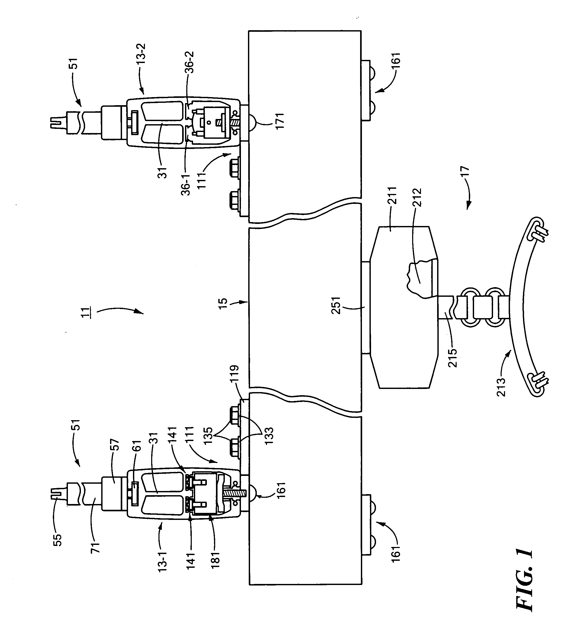
[0055]Referring now to FIG. 1, there is shown a front view of a patient positioning system constructed according to the teachings of the present invention, said patient positioning system being represented generally by reference numeral 11. For the sake of clarity, certain components of system 11 are not shown in FIG. 1 but are shown and / or described elsewhere.
[0056]System 11 may include a pair of stationary rails 13-1 and 13-2, a traverse rail 15, and a hoist system 17.
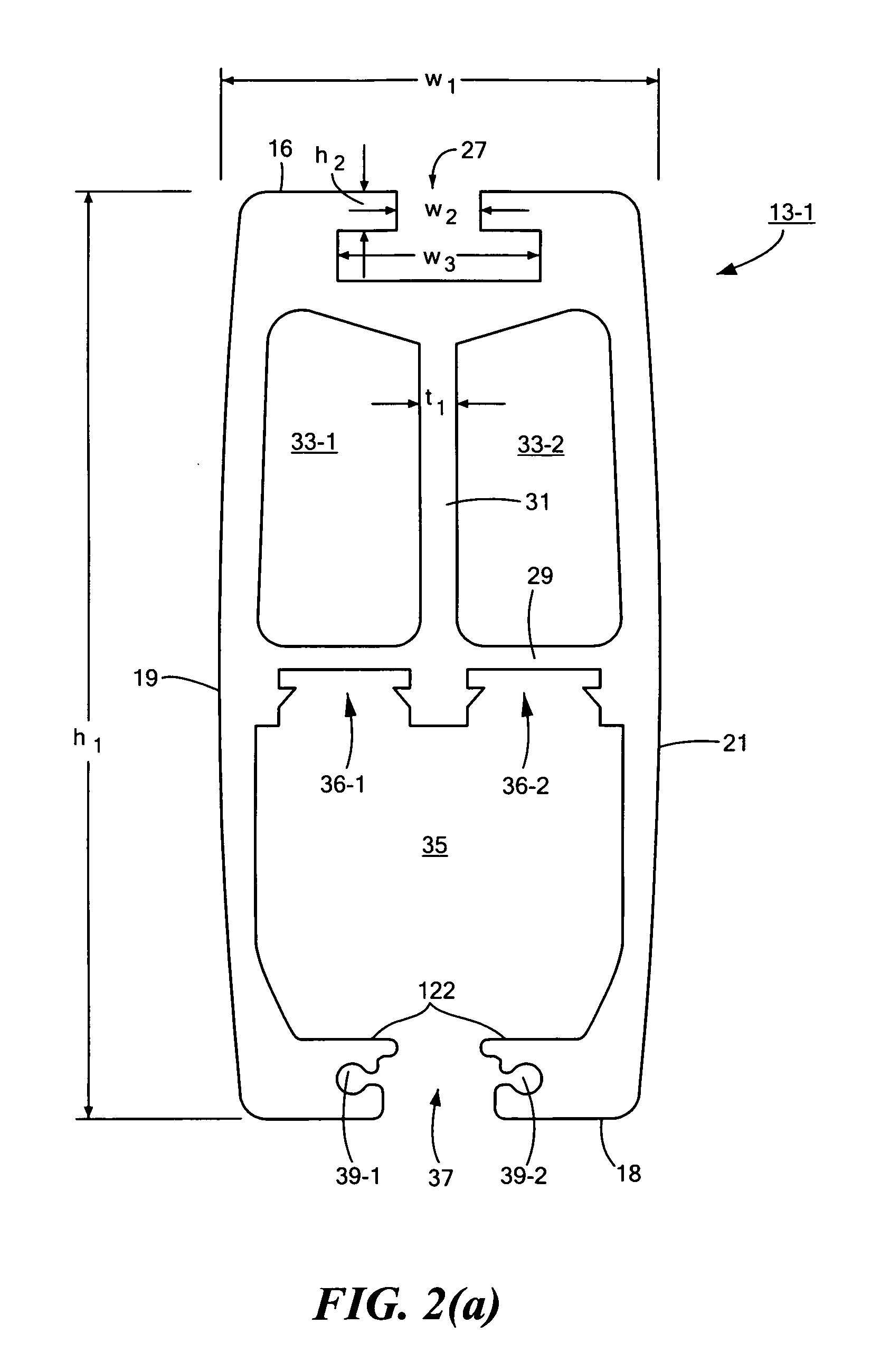
[0057]Stationary rails 13-1 and 13-2, which are substantially identical to one another in size, shape and construction, may be made of a suitably strong material, such as an extruded aluminum. Referring now to FIGS. 2(a) through 2(c), there are shown various views of rail 13-1. As can be seen, rail 13-1 may be a one-piece, substantially hollow structure shaped to include a top wall 16, a bottom wall 18, a left wall 19, a right wall 21, a substantially open front 23, and a substantially open rear 25. A channel 27, whi...
second embodiment
[0081]Referring now to FIG. 23, there is shown a fragmentary side view of a patient positioning system constructed according to the teachings of the present invention, said patient positioning system being represented generally by reference numeral 271. Certain components of system 271, such as, but not limited to one of the stationary rails, the hoist system, and electrical leads, are not shown for the sake of clarity.
[0082]System 271 may be similar in most respects to system 11, the principal difference between the two systems being that system 271 may additionally comprise a stabilizer assembly 273 for mechanically coupling stationary rail 13-1 to a building structure, which building structure may be, but is not limited to, a vertical side wall W of a room. Stabilizer assembly 273 may comprise a pair of identical stabilizer brackets 275 and 276. Bracket 275, which is also shown separately in FIGS. 24(a) through 24(b), may be a unitary member made of a strong material, such as ste...
third embodiment
[0085]Referring now to FIG. 25, there is shown a fragmentary front view, broken away in part, of a patient positioning system constructed according to the teachings of the present invention, said patient positioning system being represented generally by reference numeral 311. Certain components of system 311, such as, but not limited to, electrical leads, are not being shown for the sake of clarity.
[0086]System 311 may be similar in most respects to system 11, the principal difference between the two systems being that, whereas, in system 11, top wall 16 of traverse rail 15 may be positioned up against the bottom surface of horizontal portion 119 of bracket 115, by comparison, in system 311, bottom wall 77 of traverse rail 15 may be seated on top of the bottom surface of horizontal portion 119, with the heads of bolts 131 (not shown in FIG. 25) seated on top of bottom surface 124 of traverse rail 15. As can be appreciated, one advantage of system 311 over system 11 is that system 31...
PUM
 Abstract
Description
Claims
Application Information
 - R&D Engineer
- R&D Manager
- IP Professional
- Industry Leading Data Capabilities
- Powerful AI technology
- Patent DNA Extraction
Browse by: Latest US Patents, China's latest patents, Technical Efficacy Thesaurus, Application Domain, Technology Topic.
© 2024 PatSnap. All rights reserved.Legal|Privacy policy|Modern Slavery Act Transparency Statement|Sitemap