Connection system enabling the tightening torque of a screw terminal to be indicated

a technology of connection system and screw terminal, which is applied in the direction of connection, electrical apparatus, coupling device connection, etc., can solve the problems of large heat rise in electrical equipment units, operator's inability to indicate the actual position of screw terminal, and tendency of connection terminal loosening, etc., to ensure the quality of wiring, improve the balancing of the terminal, and ensure the effect of installation tim

Inactive Publication Date: 2011-11-03
SCHNEIDER ELECTRIC IND SAS
View PDF7 Cites 4 Cited by
  • Summary
  • Abstract
  • Description
  • Claims
  • Application Information

AI Technical Summary

Benefits of technology

[0011]According to a preferred embodiment, the first and second elements come into contact when the predetermined tightening torque is reached, said threshold distance being zero. The first and second elements can be conductive and form part of a power supply circuit of the indicating means so that the indicating means are supplied when the predetermined tightening torque is reached. For example the first element comprises two conducting tracks and the second element comprises a conducting strip. The second element is preferably located at the level of the central part of the wing and the first element extends in a direction parallel to the axis of relative movement of the terminal over a sufficient length to be facing the second element in all the relative positions of the terminal with respect to the housing. The second element can be fitted on an insulating flap fixed to a wing of the pressure device.

Problems solved by technology

Cable connection terminals can have a tendency to come loose after a long period of service and this loosening gives rise to large heat rises in electrical equipment units.
However, the operator has no practical indication on the actual position of the screw, at all times, and remains sole judge as to the clamping force applied on the electrical conductor and therefore of the contact pressure.
This lack of information may lead to a certain hesitation to the detriment of the time required to perform the operations.
Moreover, due to the fact that no indication of the actual tightening torque is available, for fear of creep occurring, the operator may be led to check the tightness of the terminal clampings regularly, even though any creep has been compensated.

Method used


Image

  • Connection system enabling the tightening torque of a screw terminal to be indicated
  • Connection system enabling the tightening torque of a screw terminal to be indicated

Examples


Embodiment Construction

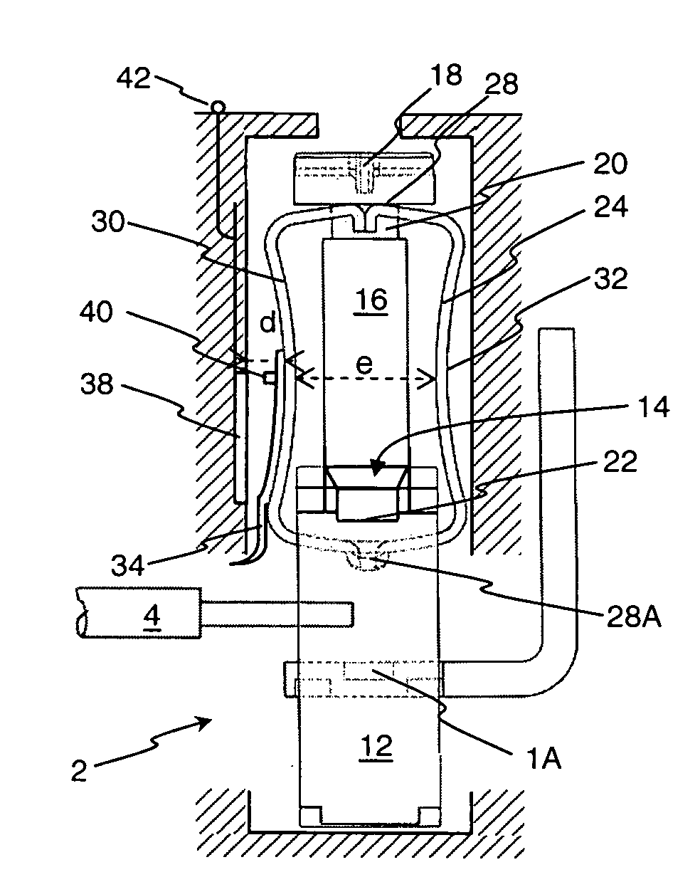
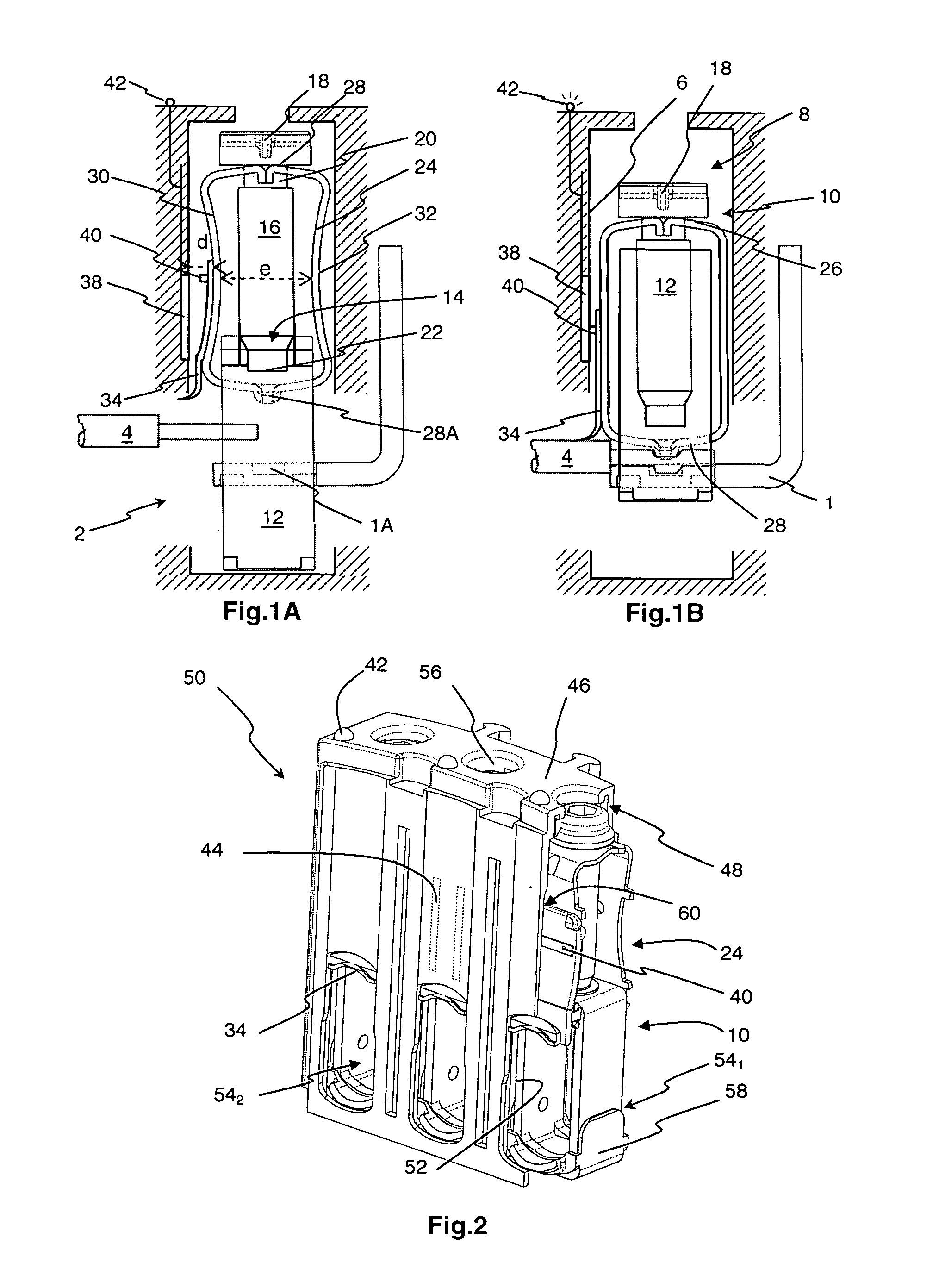
[0015]For an electric equipment unit (not illustrated), a fixed connecting strip 1 is accessible via an opening2 of the case so as to be able to associate one or more conductors 4 therewith by direct clamping. As illustrated in FIG. 1A, insulating walls 6 define a housing 8 inside the case, which housing is conventionally of rectangular parallelepipedic shape, provided with various arrangements so as to house a screw terminal 10 for connection to the fixed strip 1. The terminal 10 comprises a tunnel 12 formed by a cut and folded metal strip looped into a rigid ring defining a substantially rectangular passage which faces the access opening 2 of the case and in which the connecting strip 1 is positioned. On a small side substantially parallel to the fixed strip 1, the rigid tunnel 12 comprises a tapped hole 14 for a screw 16 to pass through, which thus moves perpendicularly to the strip 1 and enables clamping to be performed. The screw 16 comprises an operating head 18 extending a th...


PUM


Abstract

A screw terminal with creep compensation comprises a pressure device enabling a clamping energy of the terminal to be stored. According to the invention, means for detecting the tightening torque enable the user to identify the force required for connection and to check that the creep is in fact compensated. The means for detecting comprise an element securedly affixed to the pressure device and an element securedly affixed to a wall of the housing in which the terminal is fitted, the distance between the two elements being determined by means enabling indicating means to be actuated when the distance is smaller than a threshold corresponding to a predetermined tightening torque.

Description

BACKGROUND OF THE INVENTION[0001]The invention relates to a screw terminal for connecting at least one electrical conductor to a conducting strip of an electrical equipment unit. The object of the invention is more precisely to guarantee effective clamping of a terminal with creep compensation. In particular, the invention relates to a terminal comprising a device for indicating the tightening torque of the screw.STATE OF THE ART[0002]Cable connection terminals can have a tendency to come loose after a long period of service and this loosening gives rise to large heat rises in electrical equipment units. To monitor this phenomenon in order to be able to perform any necessary retightening, document EP 1 531 519 thus proposes to add a system indicating the quality of tightening, in particular a lever taking two positions.[0003]To prevent loosening itself, terminals in which means compensating creep have been developed. The document EP 1 271 697 thus presents a screw terminal comprisin...

Claims


Application Information

Patent Timeline
Patent Type & Authority Applications(United States)
IPC IPC(8): H01R3/00
CPCH01R4/302H01R4/363H01R13/6683H01R13/641H01R4/489
Inventor BUSSIERES, PIERRECOUZON, DAVIDLOIACONO, BERNARD
Owner SCHNEIDER ELECTRIC IND SAS
Why Eureka
Try Eureka