

Industrial baking tray with contoured reinforcement band
- Summary
- Abstract
- Description
- Claims
- Application Information
AI Technical Summary
Benefits of technology
Problems solved by technology
Method used
Image

Examples
Embodiment Construction
[0014]Exemplary embodiments of the present invention are now described with reference to the Figures. Although the following detailed description contains many specifics for purposes of illustration, a person of ordinary skill in the art will appreciate that many variations and alterations to the following details are within the scope of the invention. Accordingly, the following embodiments of the invention are set forth without any loss of generality to, and without imposing limitations upon, the claimed invention. With reference now to the Figures, one or more specific embodiments of this invention shall be described in greater detail.
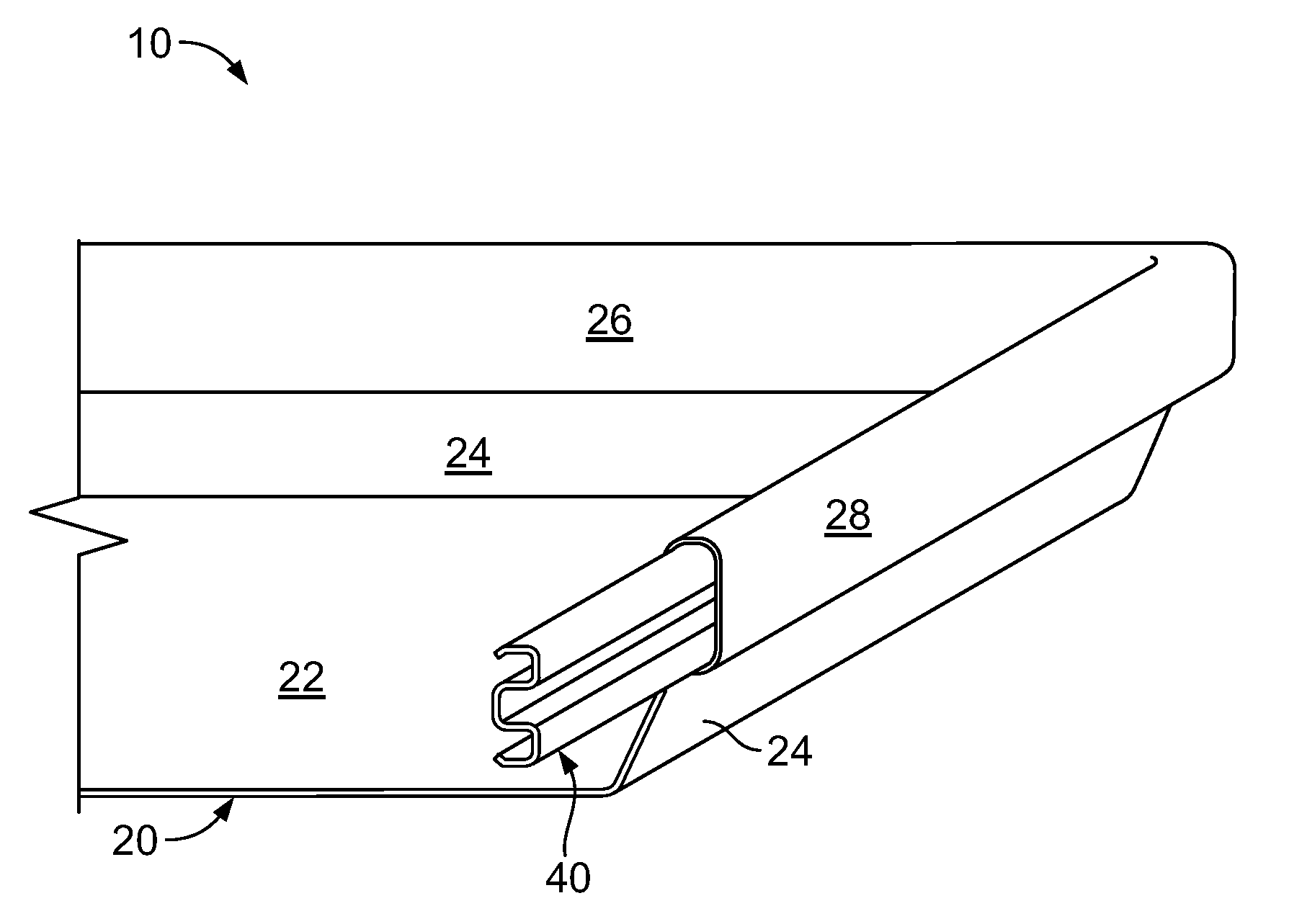
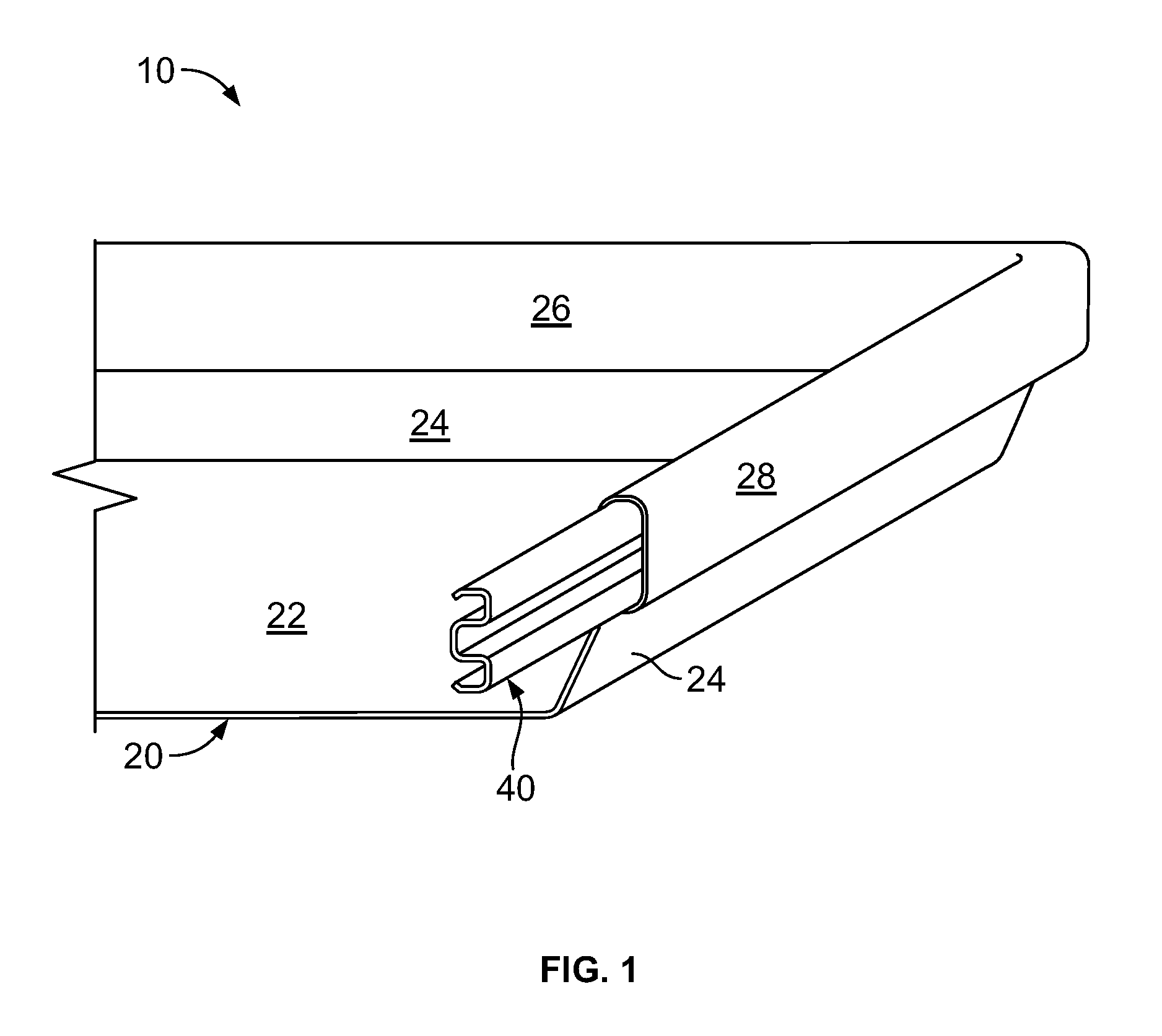
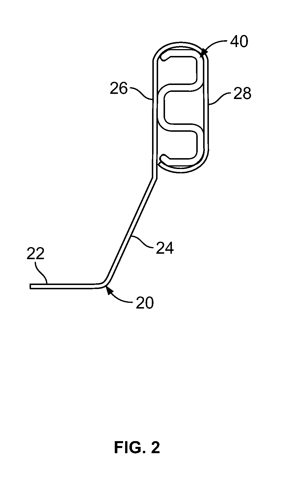
[0015]As shown in FIGS. 1-2 and 3A-B, an exemplary embodiment of baking tray assembly 10 includes baking tray 20 and contoured reinforcing band 40. Baking tray 20 further includes a horizontal bottom surface 22, an outwardly angled sidewall surface 24 surrounding bottom surface 22, and a vertical side wall surface 26 formed above angled sidewall surf...
PUM
 Abstract
Description
Claims
Application Information