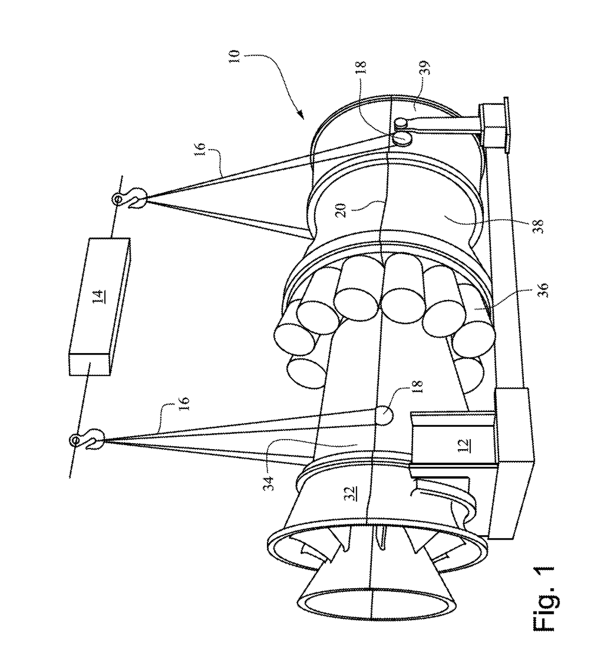
[0015]Industrial gas turbines are large and heavy engines. An industrial gas turbine may have a mass of, for example, in a range of 100 to 300 tons (90,000 kg to 272,000 kg). The dimensions of an industrial gas turbine may be, for example, a length of 30 to 50 feet (9 to 15 meters), and height and width of 12 to 20 feet (3.5 to 6 m).
[0016]Occasions arise when it is necessary to lift and move an industrial gas turbine. If rebuilding or other substantial maintenance is needed, the gas turbine may be lifted out of its operating support frame to another support frame where the gas turbine may be rebuilt or which may be used to transport the gas turbine to a maintenance facility.
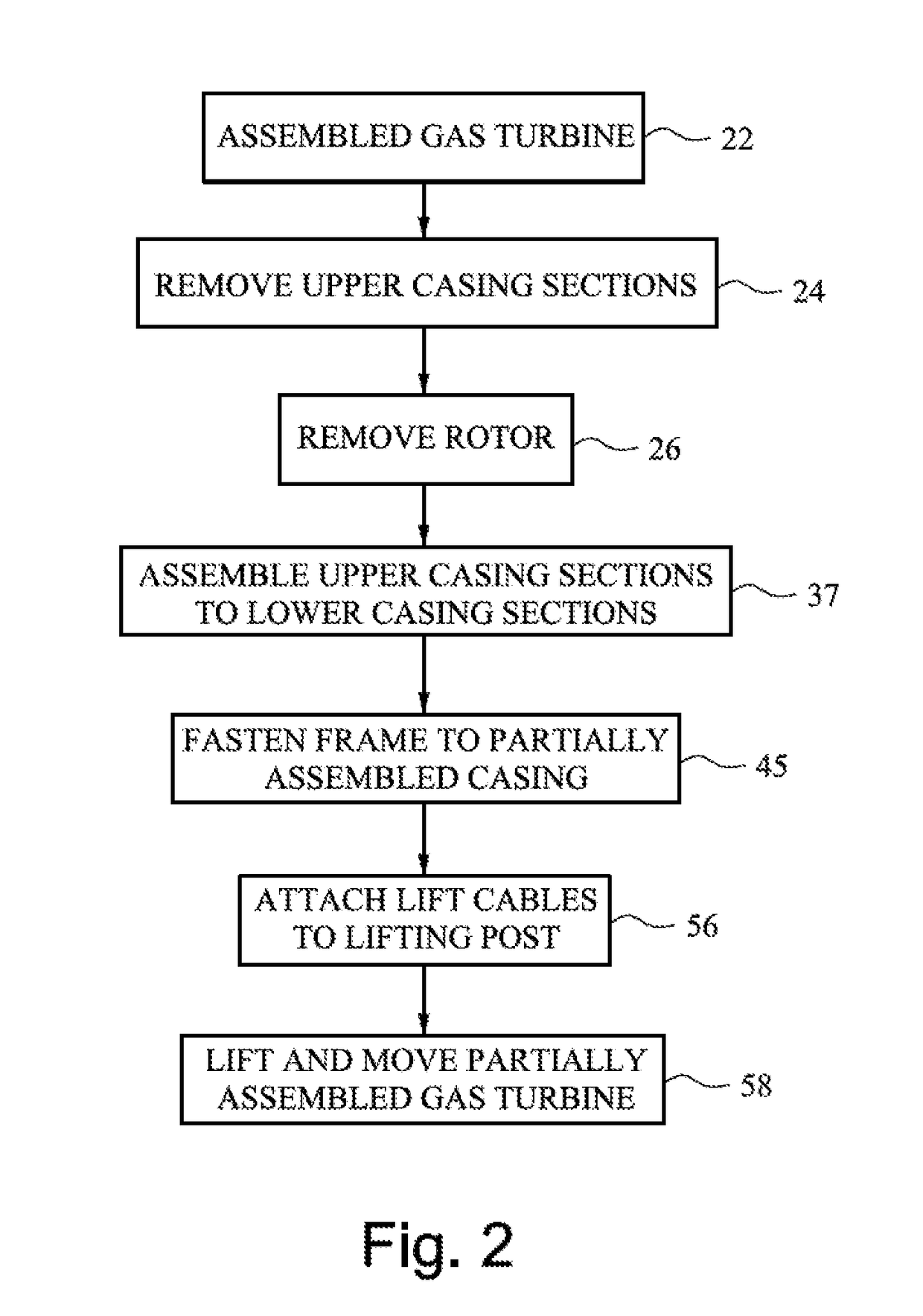
[0017]At power generation sites not suited for heavy lift cranes or lacking roads or other infrastructure sufficient to carry a fully assembled gas turbine, it has been common practice to disassemble a gas turbine while the turbine seated in its operating support frame. The sequence of disassembly includes detaching and separately removing each of the sections of the upper casing; removing the rotor from the assembled lower casing, and separately detaching and removing each section of the lower casing. This removal process is time consuming and prone to bending and thereby damaging the casing sections. Lifting a fully assembled gas turbine by cables connected to the lifting posts tends to not unduly deform the casing or create a need to realign the casing sections.
[0018]Lifting a massive gas turbine places large loads on the casing at the lifting pins and removes the supports to the casing provided by the support frame. These shifts in the loads applied to the casing could cause the casing to deform. Because the casing is fully assembled and is designed to be lifted while fully assembled, the load shifts due to lifting tend to no unduly deform the gas turbine or require substantial realignments of the casing. Also, the sections of the casing are bolted together and thus prevented from becoming misaligned with each other.
[0019]Lifting a partially assembled gas turbine and, particularly, where one or more sections of the casing are removed before the lift creates a larger potential risk that the gas turbine will deform during the lift and the casing will require alignment after the lift. The casing may deform due to the shift in the forces applied to the casing during the lift. The deformation increases the risk of misalignment between the casing and the casing section that is attached after the lift.
[0020]FIG. 1 illustrates an industrial gas turbine 10 seated on a shipping support frame 12 and attached to a crane 14 by lifting cables 16. The lifting cables attach to lifting posts 18 on opposite sides of the casing. The lifting posts 18 are generally at a mid-height of the casing and positioned near a horizontal joint 20 between the upper and lower sections of the casing of the gas turbine.
[0021]The inventors recognized a need for a better method to move a partially disassembled industrial gas turbine. The inventors conceived of a method and a frame which reduce the time and associated cost in lifting and moving a gas turbine casing and reduces the risk of deforming the casing sections during a lift of move. In the method, sections of the upper casing are temporarily removed to allow removal of the rotor, and most of the sections of the upper casing are attached to the lower casing after the rotor is removed. For those portion(s) of the upper casing not attached, a frame is attached to the lower casing and the remaining upper casing. The frame prevents deformation of the casing while the partially assembled gas turbine casing is lifted and moved.
[0022]By partially reassembling the casing after removal of the rotor, the casing becomes more structurally rigid due to the completed joints between the sections of the casing. The frame provides the casing support functions that would have been performed by the removed casing section. Because the casing sections supported by being joined to other casing sections or to the frame, all of the casing sections are less subject to deformation while be lifted and removed.
[0023]The mass, e.g., weight, of the partially assembled casings is substantially less than the mass of the gas turbine with rotor. Also the removal of one or more casing sections reduces the mass of the casings. The lower mass allows the partially assembled casings to be removed from smaller cranes and for the casings to be moved with transports, such as trucks, that are able to travel over roads that cannot support the entire weight of a complete gas turbine.
[0024]FIG. 2 is a flow chart of an exemplary method to partially disassemble and move an industrial gas turbine. The gas turbine is in a fully assembled condition with the rotor in place in step 22. The fully assembled gas turbine may be on a support frame for transport or maintenance, such as shown in FIG. 1. Alternatively, the gas turbine may be on an operational support frame on site at a power generation facility. When on an operational support frame, the inlet end of the gas turbine may be coupled to an air outlet of an air duct assembly, and the turbine exhaust end of the gas turbine may be connected to the inlet of an exhaust diffuser.
[0025]While the gas turbine is on the operational support frame and positioned between the air inlet duct and exhaust diffuser duct, the available working space around gas turbine may be small and insufficient to allow rebuilding and extensive maintenance of the gas turbine. To rebuild or conduct extensive maintenance, the gas turbine often must be moved to a maintenance facility or a site at the power generation facility that has sufficient working space around the gas turbine for rebuilding and maintenance.
[0026]In step 24, the upper casing of the gas turbine is removed to expose the rotor. In step 26, a crane above the gas turbine lifts the rotor from the lower casing of the gas turbine. The rotor may be moved separately from the casing to a site where it may be repaired, maintained or otherwise rebuilt.
[0027]FIG. 3 shows a gas turbine 10 in which the upper casing has been removed and the rotor 28 is exposed. The rotor, which includes a shaft, rows of blades for an axial compressor and rows of buckets (blades) of an axial turbine. The rotor may be lifted upward to be removed from the lower casing 30 of the gas turbine.
[0028]The lower casing 30 and the upper casing are each an assembly of casing sections. The casing sections may each extend halfway around the rotor, such that the casing sections are either upper or lower sections. An upper and lower casing section when assembled extends entirely around the rotor. Alternatively, the casing sections may be quarter sections that each extend around one quarter of the perimeter of the rotor.
[0029]The casing assembly is segmented into casing sections. For example, the casing assembly includes lower and upper sections for an inlet casing 32 (see FIGS. 1 and 2), a compressor casing 34, a combustor casing 36, a turbine casing 38, and a turbine exhaust casing 39. The upper and lower compressor sections 34 house the portion of the rotor including axial compressor blades and of stationary vanes between the rows of compressor blades. The upper and lower casing sections for the compressor and combustor may each be each a single piece component. The upper and lower combustor casing sections include openings and supports for combustion cans arranged in an annular array around the perimeter of the casing. The upper and lower turbine casing sections house the turbine section of the rotor which includes rows of stationary nozzles between the rows of the turbine buckets.
[0030]FIG. 3 shows that the lower casing sections assembled together and exposing horizontal surfaces 40 on opposite sides of the rotor and extending the length of the gas turbine. The joint surfaces 40 include bolt holes to receive the bolts or other fasteners for the casings.
[0031]In step 37 of FIG. 2 and after the rotor is removed, the casings sections are assembled together and fastened by bolts or other fasteners. Each casing section has joint surfaces, typically vertical or horizontal planar surfaces. The joint surfaces are configured to abut and align with joint surfaces of adjacent casing sections horizontal or vertical joint lines.
[0032]FIG. 4 shows a front portion of a partially reassembled gas turbine casing 42. The rotor has been removed from the casing 42 while the lower half casing sections remained assembled. The upper casing sections have been reattached to the casing by bolting each upper casing section to its corresponding lower casing sections and to adjacent upper casing sections.
[0033]The partially assembled casing 42 includes all sections of the lower half of the casing and all of the sections of the upper half except for the inlet casing. In place of the upper section of the inlet casing, a frame 44 is fastened to the partially assembled casing in step 45. The frame provides the structural support to the casing that would have otherwise been provided by the upper inlet casing.
[0034]By partially reassembling the casing 42 and fastening the frame 44 to the casing, the casing sections are all either bolted to each other or to the frame. The partial casing assembly 42 is kept in alignment because the casing sections and frame are bolted together. The bolts joining adjacent sections of the casing maintain the alignment of the bolt holes in the adjacent sections. Similarly, the bolts extending through the frame and the casing sections adjacent to the frame maintain the alignment between the bolt holes in those casings and the bolt holes in the frame.
[0035]The frame 44 has sufficient structural rigidity to prevent deformation of the casing sections to which the frame is attached. The bolt holes 46 in the frame are aligned with corresponding bolt holes in an adjacent section of the casing. By bolting the frame to the casing, the frame ensures that the casing in general and specifically the casing sections to which the frame is bolted do not deform with the partially assembled casing 42 is lifted and moved.
[0036]As shown in FIG. 5, the frame 44 includes a first bracket 48 having a vertically oriented surface and bolt holes 46 corresponding to the bolt holes in a casing section to which the first bracket is configured to be attached. The first bracket may be a metal plate having a thickness of several inches or more, e.g., three inches or 25 mm. The first bracket has two sets of bolt holes 46. Each set of bolt holes may be two, three, four or more bolt holes. Each set of bolt holes may be configured to align with a set of consecutive bolt holes on a joint surface of one of the casing sections. The two sets of bolt holes on the first bracket align with sets of bolt holes on a vertical joint surface of the upper compressor casing section. The two sets of bolt holes are on opposite sides of the upper compressor casing.
[0037]The frame also includes a second bracket 50 having a horizontal oriented surface with holes corresponding to the bolt holes in a casing section to which the second bracket is configured to attach. The second bracket may be a metal plate having the same thickness as the first bracket. The horizontally oriented surface may be a horizontal planar surface.
[0038]The second bracket may be longer than the first bracket. The second bracket spans the width of the casing along a center plane of the casing, which is the widest portion of the casing. The first bracket spans an upper (or lower) region of the casing that is offset from the center plane. The gap G1 between the two sets of bolt holes on the upper casing section aligned with the sets of bolt holes on the first bracket determines the length of the first bracket. Similarly, the gap G2 between the two sets of bolt holes on opposite sides of the lower inlet casing section determines the length of the second bracket.
[0039]The second bracket 50 may be positioned on the casing assembly to be adjacent a lifting attachment device 51. The lifting attachment device may be lifting posts, apertures to receive a hook of a crane or other device that provides a grip to receive the lifting cables of a crane. The lifting attachment device may be on opposite sides of the casing, such as on opposite sides of the lower inlet casing 54. By bolting the second bracket adjacent to the lifting attachment devices, the lifting forces applied to the casing are more directly transferred to the frame than if the second or first bracket were not proximate to the lifting attachment devices.
[0040]In step 56 (FIG. 2), lifting cables are attached to the lifting attachment devices on opposite sides of the partially assembled casing. In step 58, a crane attached to the lifting cables lifts and moves the partially assembled casing with the attached frame. The lifting and movement of the partially assembled casing is accomplished without unduly deforming the casing or creating a need for a time-consuming and expensive realignment of the casing sections.
[0041]The first and second brackets are joined by ribs 52 extending between the brackets. The ribs may be metal plates welded at each end to one of the brackets. The ends of each rib may be configured to contact one of the brackets along the entire length of the end. The welds between the rib end and the bracket may extend the length of the rib end and be on opposite sides of the rib ends. There may be three ribs wherein two of the ribs are near the bolt holes in the brackets and the third rib is at a center region of the frame. The thickness of the ribs may be substantially, e.g., within fifteen percent, of the thickness of either of the brackets.
[0042]The ribs may be each in a plane parallel to the axis of the casing. By orienting the ribs in a plane parallel to the casing axis, the forces applied in an axial direction against the upper or lower brackets are transmitted along the centerline of the ribs with minimal torsion being applied to the ribs.
[0043]The upper ends of the outer two ribs may be welded to ends of the first bracket. The lower ends of the outer two ribs may be welded to an upper planar surface of the second bracket and be welded inward of the sets of the bolt holes on the second bracket.
[0044]The mass of the frame is substantially, e.g., less than one third, of the mass of the section of the casing being replaced by the frame. For example, the inlet casing sections typically have a large mass relative to the other casing sections. Removing the upper inlet casing section reduces substantially, e.g., by over twenty percent, the mass of the casing of the gas turbine. The frame may be less than one third the mass of the upper inlet casing section. By replacing the upper inlet casing section with the frame the mass of the remaining gas turbine casing assembly may be reduced by ten to fifteen percent. The reduction in mass may be sufficient to allow the partially assembled gas turbine casing to be lifted by a crane from a particular power generation site. Similarly, the reduction in mass may be sufficient to allow the partially assembled gas turbine casing to be transported over the roads leading from the power generation site.
[0045]FIGS. 6 and 7 show plan views of the first and second brackets. These views show the pattern of the bolt holes in brackets 48, 50. The number and pattern of bolt holes are machined, e.g., drilled, and with sufficient precision to accurately alight with the bolt holes on the casing sections to which the brackets attach. Each group of bolt holes may be arranged in an arc as shown in FIGS. 6 and 7, or in a straight or curvilinear line. The arrangement of bolts holes will depend on the shape of the surface of the casing to which the bracket is to be fastened.
[0046]The bolt holes in the brackets are selected and positioned such that when bolts are inserted through the bolt holes and into the section casings, the bolts are sufficiently supported by the brackets to ensure that the section casing maintain proper alignment. Proper alignment is needed so that the missing casing section can be attached to the partial assembly of casing sections, preferably without extensive realignment of the missing casing section with the assembly of casing sections.
[0047]The ribs 52 may be attached to the first and second bracket proximate to, e.g., within five inches of, one of the bolt holes. By minimizing the distance between the rib and the nearest bolt hole to the rib, the moment forces are reduced that are applied to the bracket by the bolts and the rib.
[0048]The number of support ribs, thickness of the brackets and ribs, and number and location of the bolt holes are dependent on the mass and size of the gas turbine. To design the frame, including selecting the number of ribs, thicknesses of the brackets and ribs and location and number or bolt holes, a finite element analysis (FEA) may be performed to model the partially assembled casing and frame. The FEA model may be used to determine whether the partially assembled casing with the frame may be lifted and moved without unduly deforming the casing or creating a need for an extensive realignment of the casing sections.
[0049]While the invention has been described in connection with what is presently considered to be the most practical and preferred embodiment, it is to be understood that the invention is not to be limited to the disclosed embodiment, but on the contrary, is intended to cover various modifications and equivalent arrangements included within the spirit and scope of the appended claims.