Shutter device used for exposure in lithography machine, and method for use thereof

Active Publication Date: 2019-12-05
SHANGHAI MICRO ELECTRONICS EQUIP (GRP) CO LTD
View PDF3 Cites 0 Cited by
  • Summary
  • Abstract
  • Description
  • Claims
  • Application Information

AI Technical Summary

Benefits of technology

[0032]In the shutter device for use in exposure by photolithography machine and the method of using the shutter device, a shutter blade includes a rotation center and, disposed in correspondence with the rotation center, at least one open portion and at least one shielding portion, the rotation center coupled to a rotating motor which drives the shutter blade to rotate so that the shutter is opened and closed to enable and disable exposure. In addition, the shielding portion includes a hollow portion which significantly reduces the mass of the shutter blade, facilitating the control over the rotation of the shutter blade and improving the exposure dose control accuracy.

Problems solved by technology

However, due to the structural limitations of the conventional mechanical shutter, the shutter opening and closing time is already close to the limit, and increasing the power of the shutter simply increases the burden on the control system.
Further, frequent overpowered operations may impair the stability of the system.
However, in order to achieve a shorter shutter opening and closing

Method used


Image

  • Shutter device used for exposure in lithography machine, and method for use thereof
  • Shutter device used for exposure in lithography machine, and method for use thereof
  • Shutter device used for exposure in lithography machine, and method for use thereof

Examples


Example

Embodiment 1

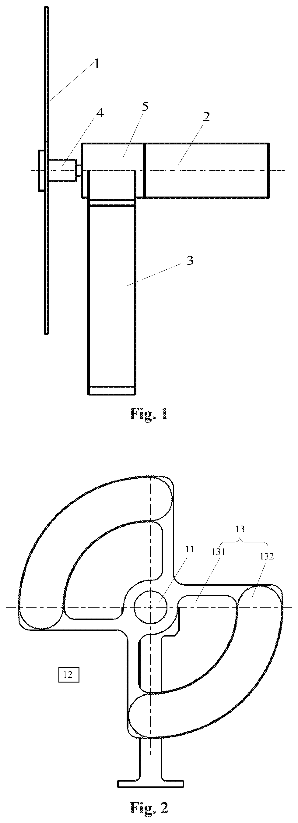
[0044]As shown in FIGS. 1 to 7, the present invention provides a shutter device for used in exposure by a photolithography machine, including: a shutter blade 1; a rotating motor 2 for driving the shutter blade 1 to rotate; a controller (not shown) in electric connection with the rotating motor 2; and a supporter 3 for holding the rotating motor 2. The shutter blade 1 includes a rotation center 11 and at least one open portion 12 and at least one shielding portion 13 which are disposed in correspondence with the rotation center 11. The rotation center 11 is coupled to the rotating motor 2. The rotating motor 2 drives the shutter blade 1 to rotate so that the shutter is opened and closed to enable and disable exposure. In addition, during the enabling and disabling of exposure, the rotating motor 2 and / or shutter blade 1 rotate at a non-zero speed.

[0045]With continued reference to FIG. 1, between the rotation center 11 of the shutter blade 1 and the rotating motor 2 may b...

Example

Embodiment 2

[0063]As shown in FIG. 8, this Embodiment differs from Embodiment 1 in that the shutter blade 1 has one open portion 12 and one shielding portion 13. Each of the open portion 12 and the shielding portion 13 has a central angle of 180 degrees. Additionally, the speed reducer 5 is omitted, and the shutter blade 1 is directly driven by the rotating motor 2 instead. Preferably, the shielding portion 13 includes an inner hollow portion 131 and an outer scanning light shielding portion 132 that is concentric with the inner hollow portion with respect to the rotation center 11. The hollow portion 131 may be fan-shaped and can effectively reduce the mass of the shutter blade, which facilitates the control over the rotation of the shutter blade and hence improves the exposure dose control accuracy. The scanning light shielding portion 132 may be annular-shaped which can block light during the rotation of the shutter blade 1 and thus disable exposure. In this Embodiment, as the sh...

Example

Embodiment 3

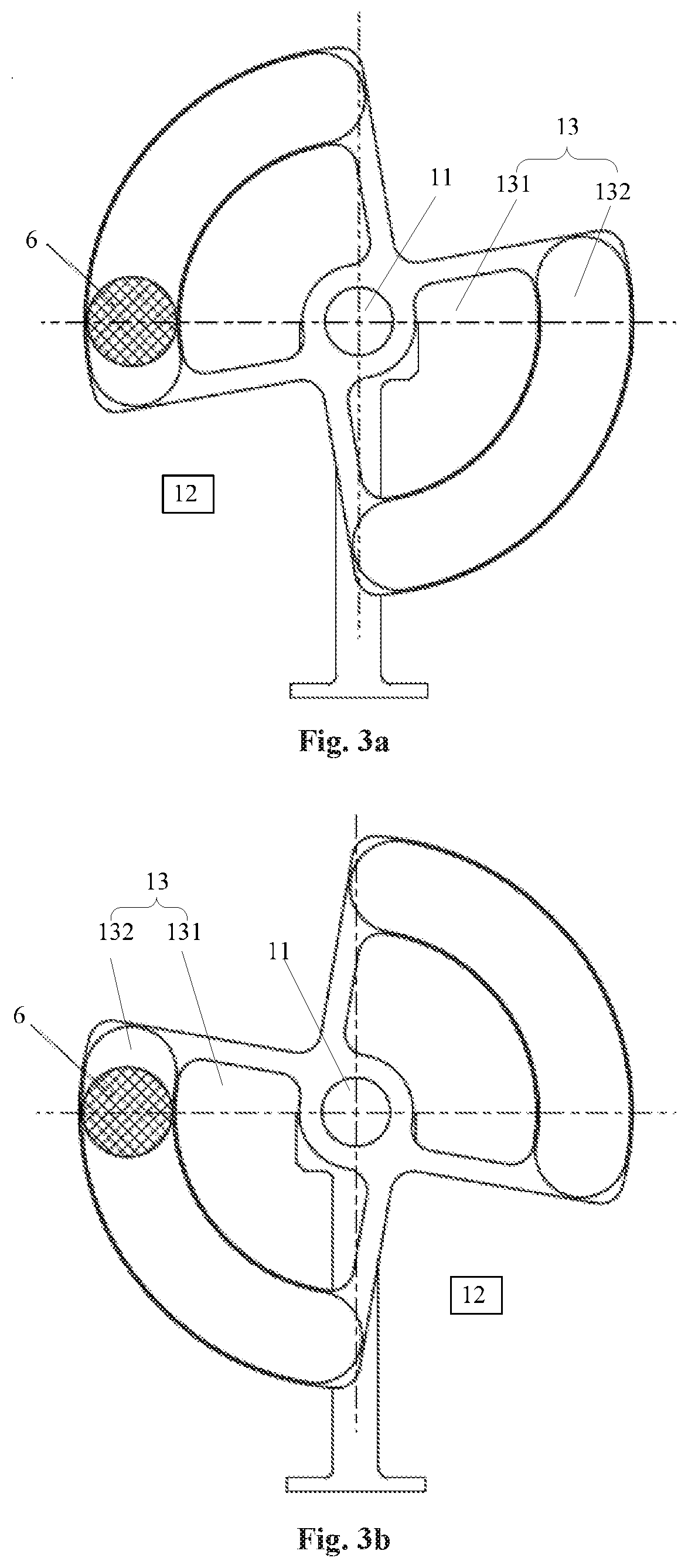
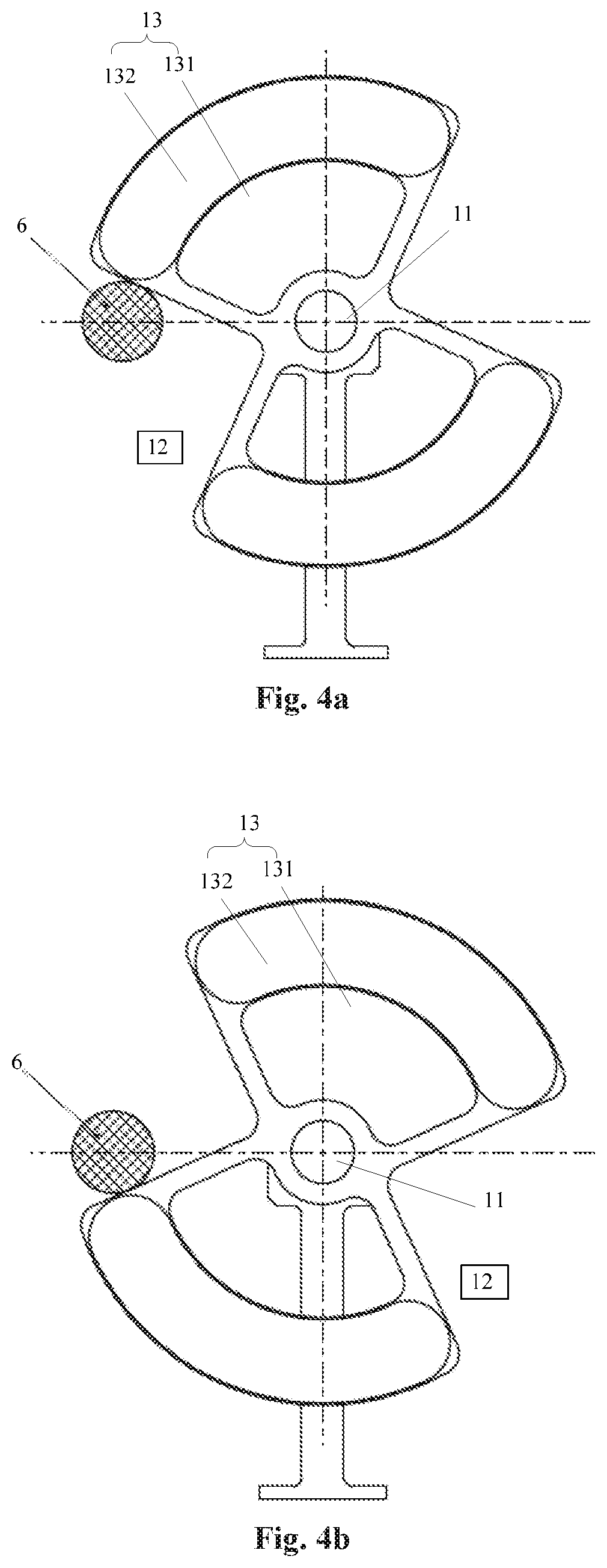
[0071]This Embodiment differs from Embodiment 1 in that the shutter blade 1 has three open portions 12 and three shielding portions 13, which are staggered one another around the rotation center 11 and each of the open portions 12 and the shielding portions 13 has a central angle of 60 degrees. Preferably, each of the shielding portions 13 includes an inner hollow portion 131 and an outer scanning light shielding portion 132 that is concentric with the inner hollow portion with respect to the rotation center 11. The hollow portion 131 may be fan-shaped and can effectively reduce the mass of the shutter blade, which facilitates the control over the rotation of the shutter blade and hence improves the exposure dose control accuracy. The scanning light shielding portion 132 may be annular-shaped which can block light during the rotation of the shutter blade 1 and thus disable exposure.

[0072]During a constant-speed rotation cycle experiencing the partially-open fully-open an...


PUM


Abstract

A shutter device for use in exposure by a photolithography machine and a method of using the shutter device are disclosed. The device includes a shutter blade (1); a rotating motor (2) for driving the shutter blade (1) to rotate; a controller in electric connection with the rotating motor (2); and a supporter (3) for supporting the rotating motor (2). The shutter blade (1) includes a rotation center (11) and, disposed in correspondence with the rotation center (11), at least one open portion (12) and at least one shielding portion (13). The rotation center (11) is coupled to the rotating motor (2) which drives the shutter blade (1) to rotate so that the shutter device opening and closure are accomplished to enable and disable exposure. The shielding portion (13) includes a hollow portion (131) which significantly reduces the mass of the shutter blade (1), thereby facilitating the control over the rotation of the shutter blade (1). Under the control of the controller, the opening and closing of the shutter is accomplished during rotation of the shutter blade (1) at a constant speed, while the acceleration and deceleration of the shutter blade (1) take place in the period when the shutter device is in a closed state, which is relatively long and allows a large stroke. This significantly reduces the required torque of the rotating motor (2) and effectively shortens the shutter opening and closing time.

Description

TECHNICAL FIELD[0001]The present invention relates to the manufacturing of photolithography equipment and, more particular, to a shutter device for use in exposure by a photolithography machine and a method of using the shutter device.BACKGROUND[0002]Photolithography is a technique for printing a pattern with features onto the surface of a substrate. A commonly-used substrate is a semiconductor wafer or a glass substrate having a surface coated with a light-sensitive material (e.g., photoresist). During a photolithography process, a wafer is placed on a wafer stage and the pattern is projected onto the surface of the wafer by means of an exposure device incorporated in the photolithography machine.[0003]One of the important metrics for assessing the performance of a photolithography machine is exposure dosage, because the development of the photoresist will be affected at excessively high or low exposure doses. For this reason, exposure dose control accuracy poses a direct impact on...

Claims


Application Information

Patent Timeline
IPC IPC(8): G03F7/20
CPCG03F7/70191G03F7/70366G03F7/70558G03F7/20H01L21/00G03F7/7055G03F7/70758G03F7/70825
Inventor CHEN, MENGLAIZHANG, FUPING
Owner SHANGHAI MICRO ELECTRONICS EQUIP (GRP) CO LTD
Why Eureka
Try Eureka