Reinforced heat exchanger
- Summary
- Abstract
- Description
- Claims
- Application Information
AI Technical Summary
Benefits of technology
Problems solved by technology
Method used
Image
Examples
first embodiment
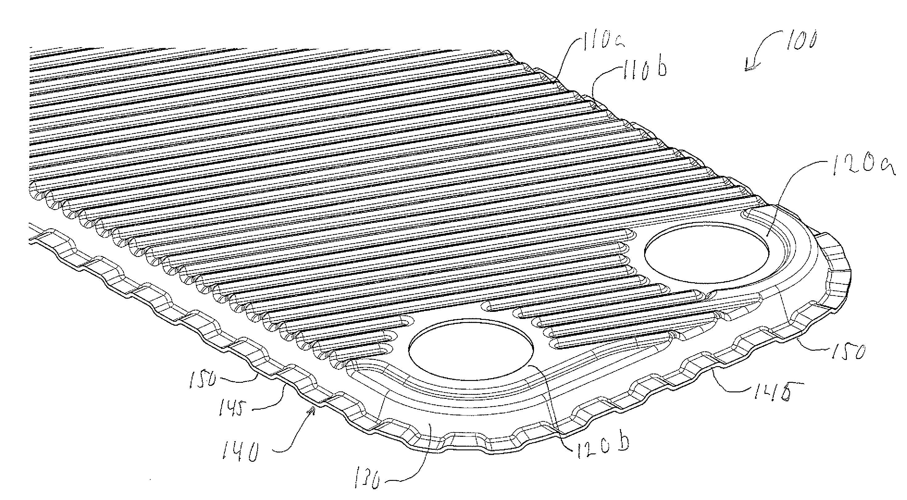
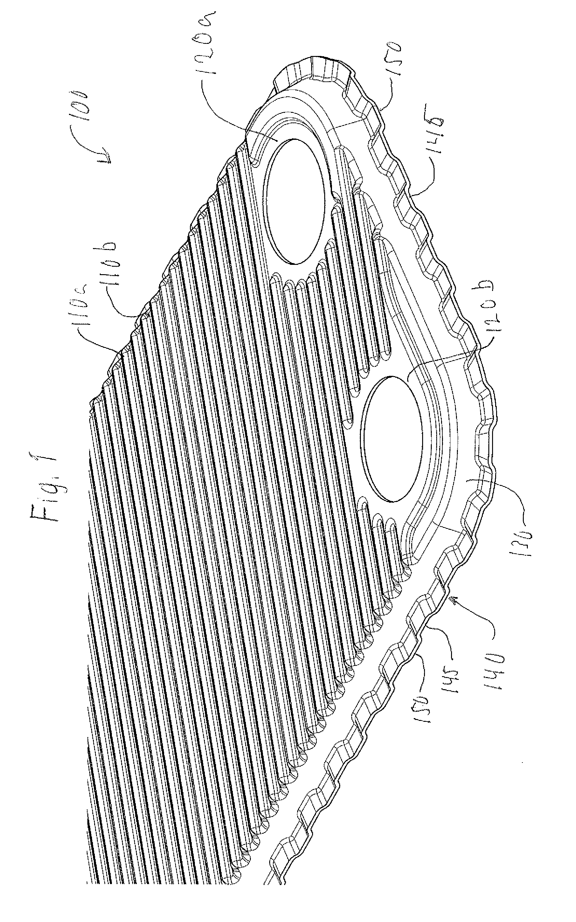
[0020]In FIG. 1, a heat exchanger plate 100 according to the present invention is shown. The plate 100 extends in a general plane, and is provided with a pressed pattern of ridges 110a and groove 110b. Moreover, the plate 100 is provided with port openings 120a-d (only the port openings 120a and 120b are shown); neighboring openings are provided on different heights; in the shown figure, the port opening 120b is provided on a height equal to the height of the ridges 110a, whereas the port opening 120a is provided at the height of the grooves 110b.
[0021]A skirt 130 is provided in a basically perpendicular direction vis-á-vis the plane P. The skirt 130 surrounds the area provided with the ridges 110a and the grooves 120b and the port openings 120a-d; skirts of neighboring plates are adapted to overlap one another such that a seal between the plates is achieved. At the end of the skirt opposite the pressed pattern and the port openings, a reinforcement portion 140 is provided. The rei...
second embodiment
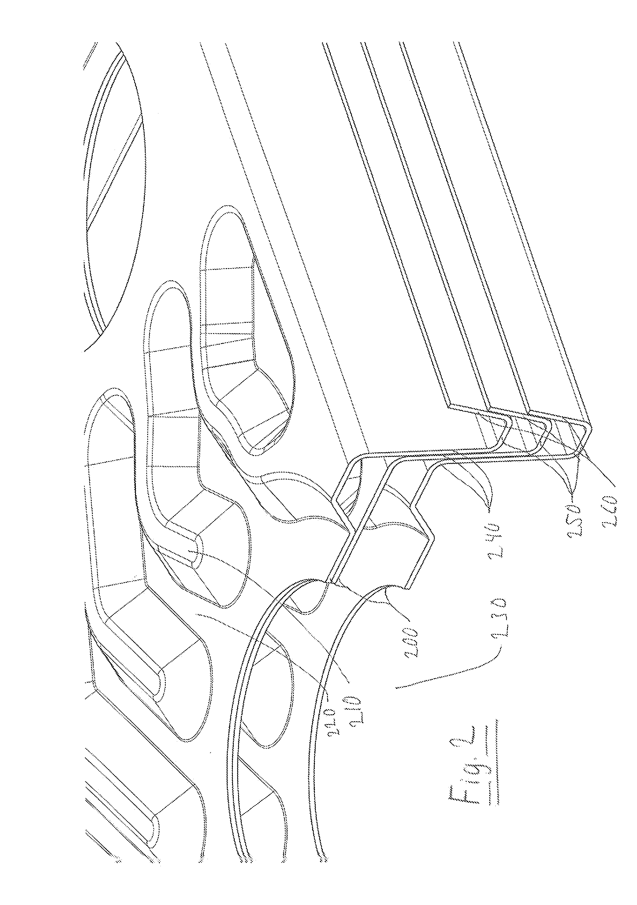
[0027]the invention, shown in FIG. 2, comprises a number of heat exchanger plates 200 provided with a pressed pattern of ridges 210 and grooves 220 arranged to hold the heat exchanger plates on a distance from one another under formation of flow channels for media to exchange heat. The heat exchanger plates are moreover provided with port openings 230 (only one partially shown in FIG. 2). In order to seal off the flow channels, skirts 240 are arranged along edges of the heat exchanger plates, such skirts 240 being arranged such that an upper side of a skirt of a first heat exchanger plate will contact a lower side of a skirt of a second heat exchanger plate stacked upon the first plate.
[0028]On an outside of the skirt 240, a reinforcement ribbon 250 is provided. The reinforcement ribbon is pressed such that an outer surface 260 extends such that it forms a truncated V with respect to the skirt 240.
[0029]Preferably, the outer surface 260 of one heat exchanger cooperates with the oute...
third embodiment
[0032]In FIG. 3, a heat exchanger 300 equaling the second aspect as described above, of the present invention is shown. The heat exchanger comprises a number of heat exchanger plates 310, all of which being provided with ridges 320 and grooves 330 to form flow channels for media to exchange heat, port openings (not shown) and a skirt 335 surrounding the heat exchanger plate and providing a seal for the flow channels by contact between skirts 335 of neighboring plates 300.
[0033]Moreover, the heat exchanger plates 300 according to the third embodiment comprises a reinforcing portion 340, which resembles the reinforcement area 140 of the heat exchanger plates according to the first embodiment in that it comprises pressed ridges 350 and grooves 360. However, the ridges and groves of the third embodiment differ from the ridges and grooves of the first embodiment in that the ridges 350 and grooves 360 of one heat exchanger plate of the third embodiment are located to be placed inline wit...
PUM
 Abstract
Description
Claims
Application Information
 - R&D
- Intellectual Property
- Life Sciences
- Materials
- Tech Scout
- Unparalleled Data Quality
- Higher Quality Content
- 60% Fewer Hallucinations
Browse by: Latest US Patents, China's latest patents, Technical Efficacy Thesaurus, Application Domain, Technology Topic, Popular Technical Reports.
© 2025 PatSnap. All rights reserved.Legal|Privacy policy|Modern Slavery Act Transparency Statement|Sitemap|About US| Contact US: help@patsnap.com


