Trap

a technology for traps and animals, applied in the field of traps, can solve the problems of reducing the efficiency of pest control programmes, unpractical, unsatisfactory emptying of traps, etc., and achieve the effect of restricting around the animal

Active Publication Date: 2011-12-08
GOODNATURE
View PDF31 Cites 10 Cited by
  • Summary
  • Abstract
  • Description
  • Claims
  • Application Information

AI Technical Summary

Benefits of technology

The patent describes a kill mechanism that includes a constriction mechanism to kill animals. This constriction mechanism can be a noose, cord, strap, cable, or moving bar arrangement that is designed to constrict around the animal. The predetermined period of time for the constriction is at least three minutes. The trap also has a time delay arrangement that causes the animal to be released and the trap to be reset at the end of the predetermined period. The technical effect of this invention is to provide a reliable and effective way to kill animals in a safe and efficient manner.

Problems solved by technology

The technical problem addressed in this patent text is to provide an improved animal trap that does not require the user to empty and reset the trap, thereby reducing the amount of labor required and improving the efficiency of pest control programs.

Method used


Image

  • Trap
  • Trap
  • Trap

Examples


Embodiment Construction

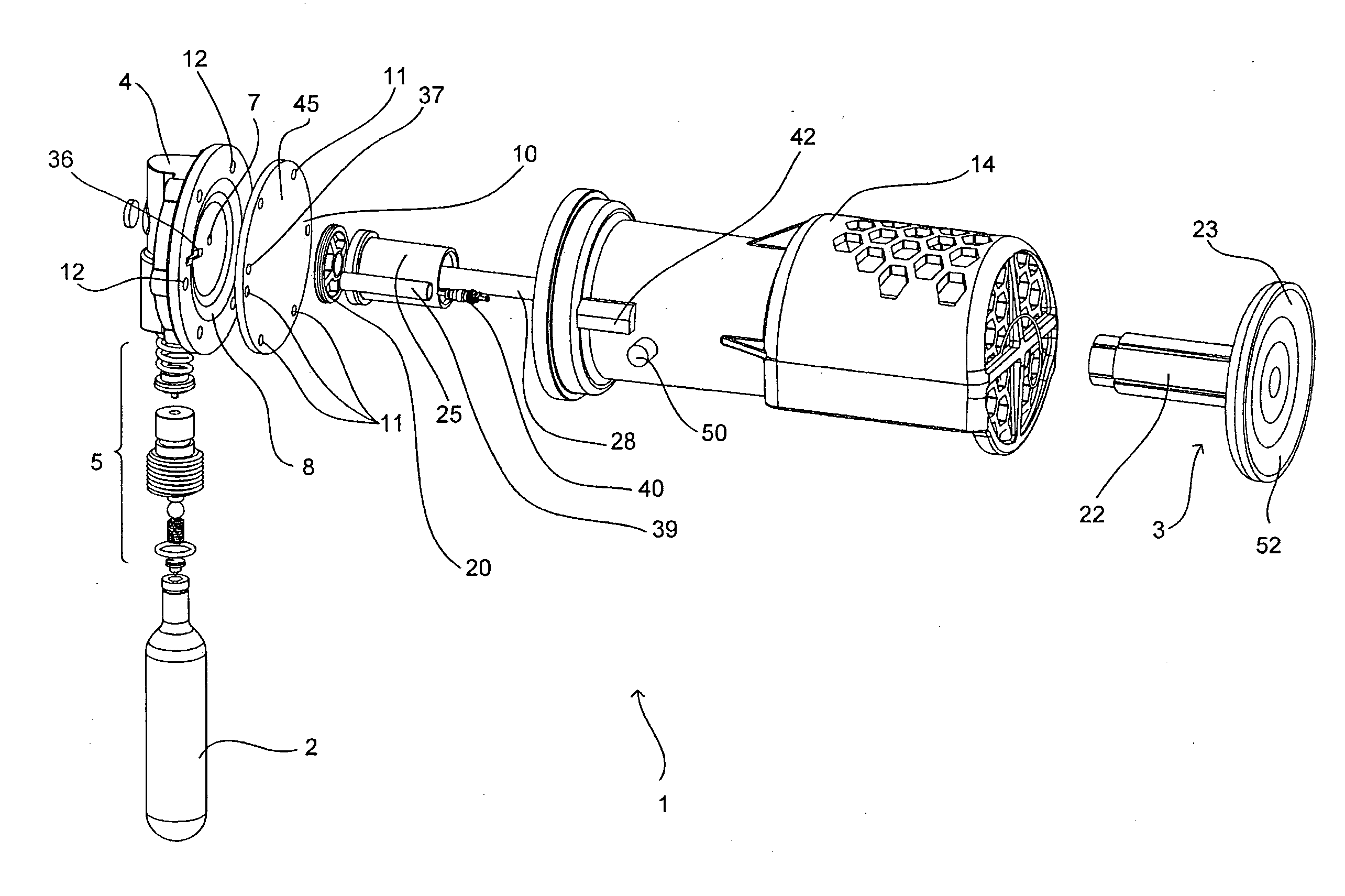
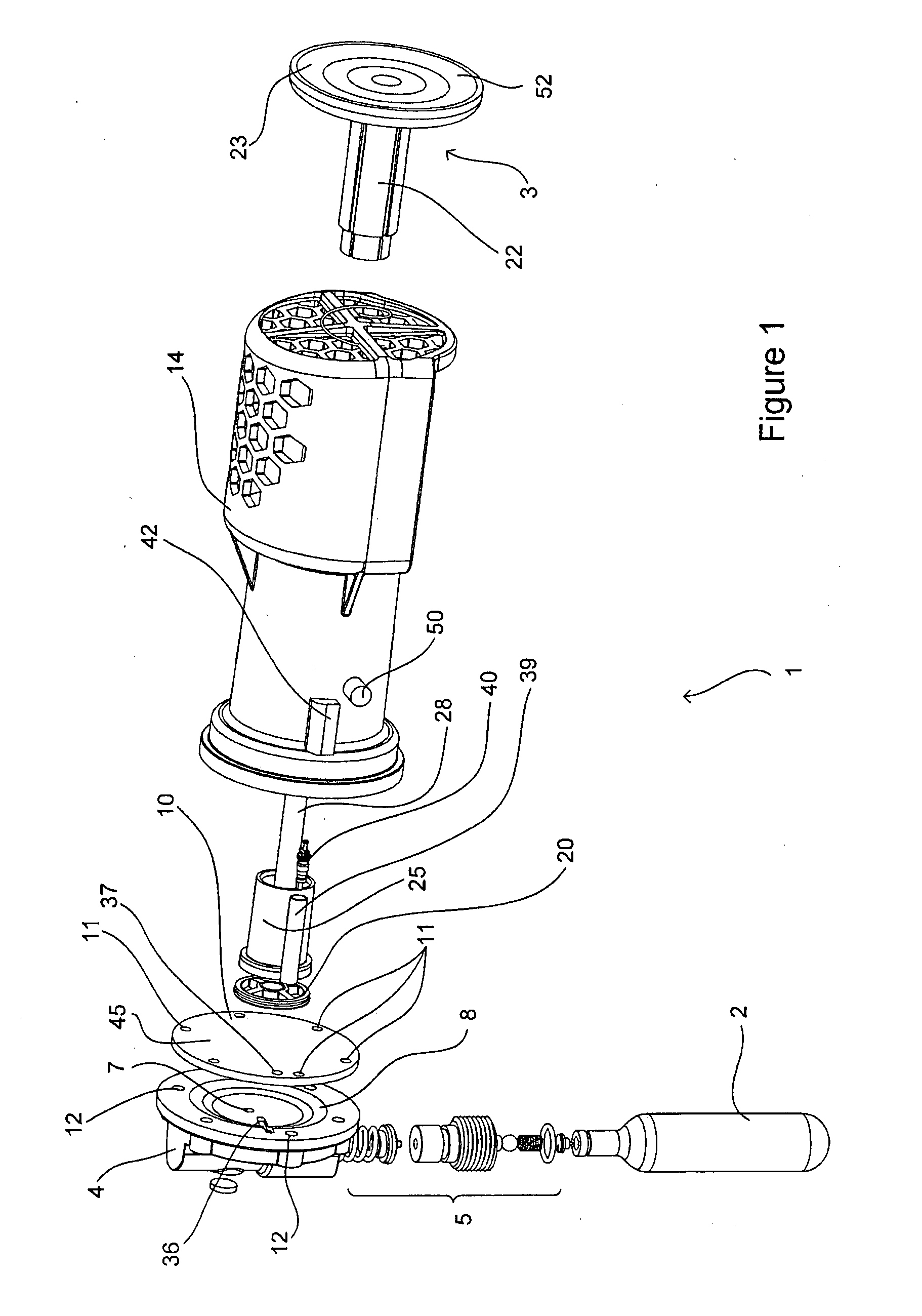
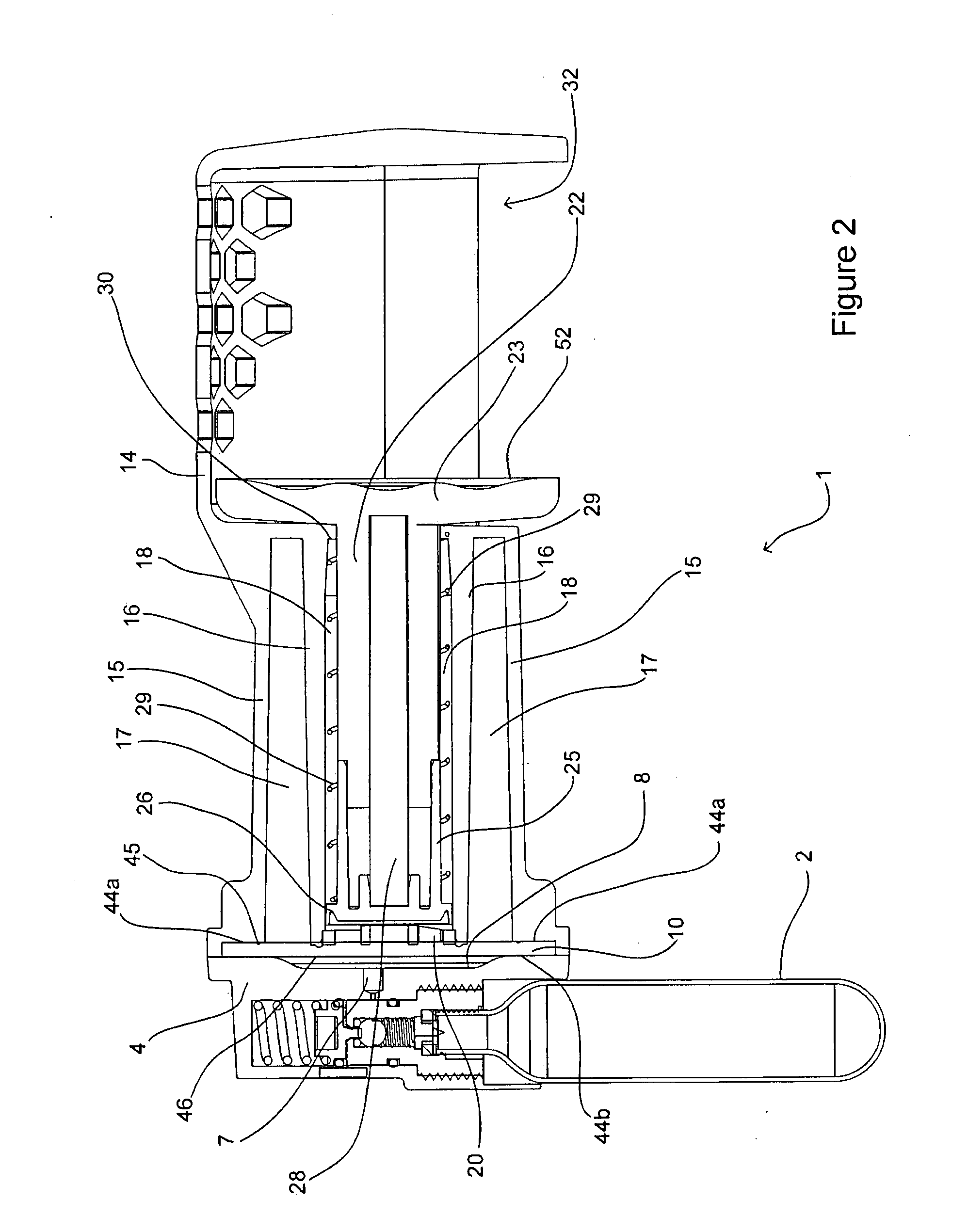
[0072]FIG. 1 is an exploded view, FIG. 2 is a cross-section and FIG. 3 is a side view of a trap 1 according to one embodiment. The trap 1 includes a source of compressed gas 2, in the embodiment shown as a canister. The trap 1 also includes a flow control arrangement (described in detail below) designed to control gas flow for operation of a kill mechanism 3 by compressed gas drawn from source 2.

[0073]The source 2 of compressed gas may be a canister (such as a readily available CO2 canister) cylinder or any form of suitable reservoir for holding pressurised gas. The gas may be stored in a solid form within the source, being released from the source as a gas (as is the case with some CO2 canisters). Such canisters are easily replaced when empty or as part of a routine servicing of the trap. Other sources of compressed gas can be re-pressurised. For example, some reservoirs could be re-pressurised using a bicycle pump or suitable electric pump. The use of compressed gas therefore prov...


PUM


Abstract

An animal trap is powered by compressed gas and includes a trigger mechanism and kill mechanism. The trap is preferably self-resetting. A variety of sources of compressed gas may be used, and different kill mechanisms may also be used. The trap is particularly suited to applications where low-maintenance traps are required, because it uses a simple, reliable mechanism which can kill a number of animals over a long period of time without requiring maintenance or manual resetting.

Description


Claims


Application Information

Patent Timeline
Owner GOODNATURE
Why Eureka
Try Eureka