
Apparatus and method for manipulating tissue

a technology of tissue manipulation and apparatus, applied in the field of medical equipment and methods, can solve the problems of obesity early mortality, large number of health-related problems,

Inactive Publication Date: 2012-01-12
LIDDICOAT JOHN R +1
View PDF2 Cites 2 Cited by
  • Summary
  • Abstract
  • Description
  • Claims
  • Application Information

AI Technical Summary

Benefits of technology

"The present invention provides an apparatus and method for manipulating tissue to provide therapeutic benefits. The apparatus includes a shaft with a distal end and a proximal end, and a plurality of effector mechanisms mounted to the distal end of the shaft. The effector mechanisms are configured to capture tissue against the shaft and maintain it in such engagement while suction is maintained. The apparatus also includes an actuating mechanism mounted to the proximal end of the shaft, which can actuate the effector mechanisms to reconfigure tissue. The technical effect of the invention is to provide a novel apparatus and method for reconfiguring tissue that can provide therapeutic benefits."

Problems solved by technology

Severe obesity is associated with a large number of health-related problems.
Several of these problems are underlying causes of earlier mortality for obesity.

Method used


Image

  • Apparatus and method for manipulating tissue
  • Apparatus and method for manipulating tissue
  • Apparatus and method for manipulating tissue

Examples


first preferred embodiment

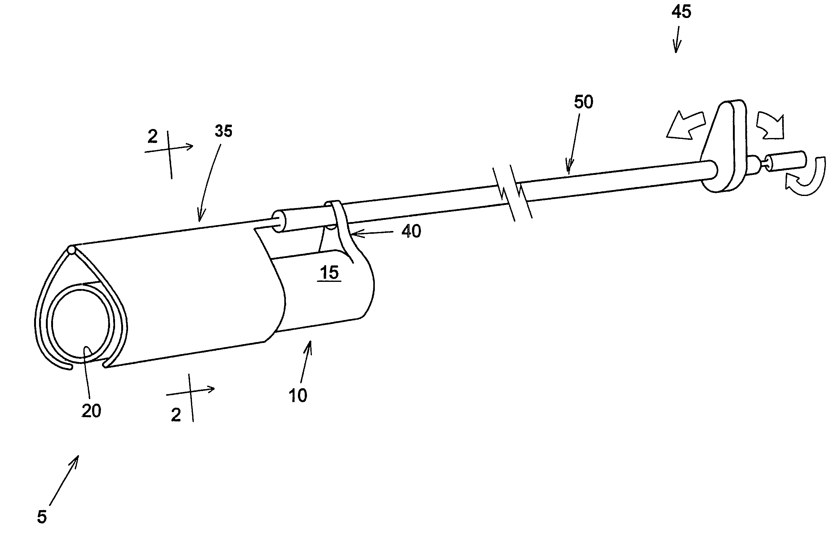
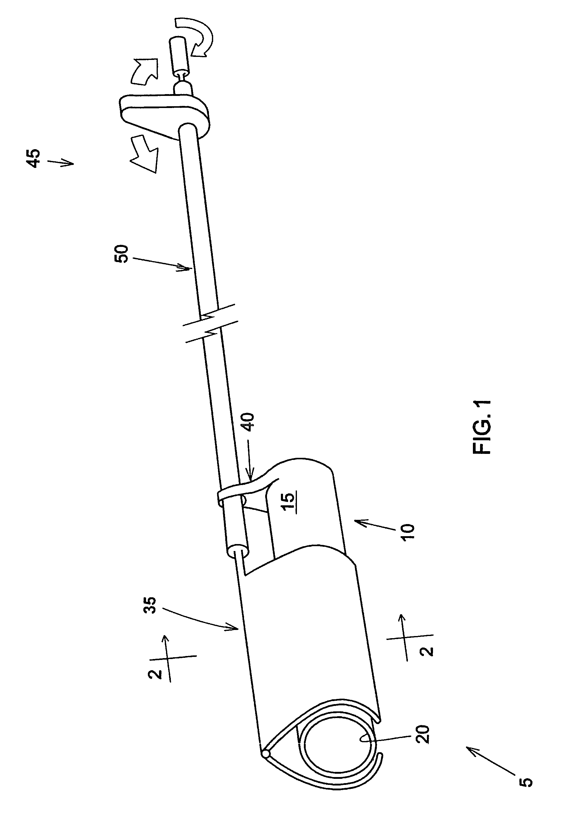
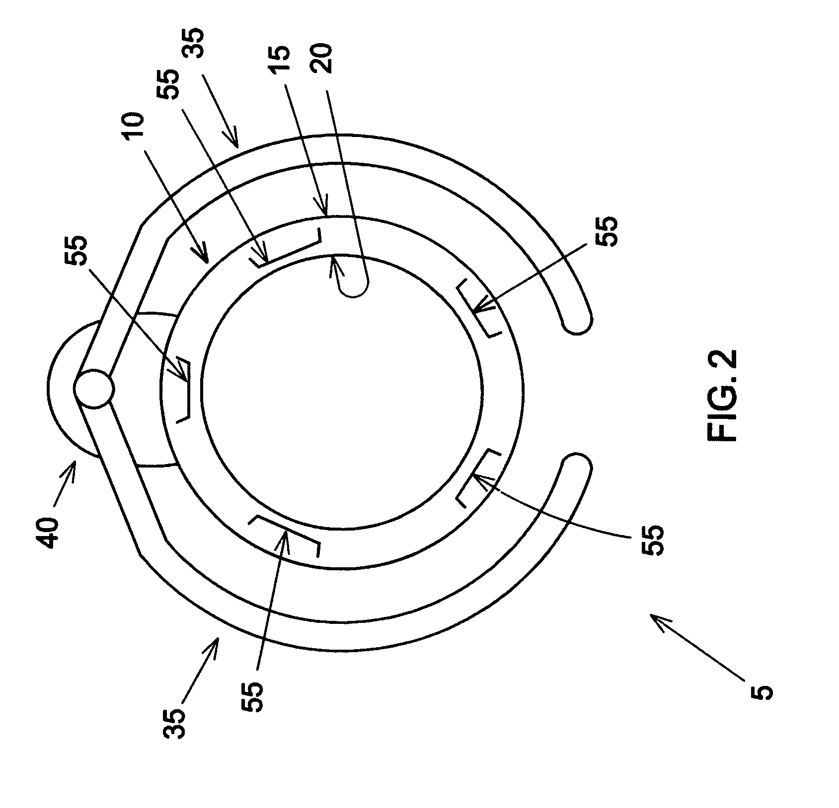
[0089]Looking now at FIGS. 1-4, in a first preferred embodiment of the present invention, an apparatus 5 comprises a flexible tube 10 having an outer surface 15 and an inner lumen 20. Various devices (e.g., working tools, scopes, etc.) can pass through inner lumen 20. Pods 25 (shown in FIGS. 3 and 4 but omitted from the remaining drawings for purposes of clarity) are provided in the outer surface 15 of flexible tube 10, whereby tissue may be drawn to the outer surface 15 of flexible tube 10. Conduits 30 (shown in FIGS. 3 and 4 but omitted from the remaining drawings for purposes of clarity) are formed in the side wall of flexible tube 10 and supply suction to pods 25.

[0090]Effector mechanisms 35 are configured to concentrically close about flexible tube 10. Preferably, effector mechanisms 35 are pivotally mounted to flexible tube 10 by a mount 40, with actuating mechanism 45 (preferably including a flexible tube 50) being used to position flexible tube 10 and effector mechanisms 35 ...

second preferred embodiment

[0097]Looking now at FIGS. 13-18, in a second preferred embodiment of the present invention, an apparatus 105 comprises a flexible shaft 110 with an actuator end 115 and an effector end 120. The effector end 120 has one or more effector mechanisms 125. The distal end of the device has a hollow tube 130 with a central lumen 135 (FIGS. 14 and 16). Objects such as a working instrument, endoscope, etc. can pass through the central lumen 135.

[0098]Effector mechanism 125 is adapted to open and close about an end pivot 140. A septum 145 has one portion anchored to effector mechanism 125 and another portion anchored to hollow tube 130. In one preferred construction, septum 145 enters the interior of effector mechanism 125 via a slot 150 (FIG. 16), and septum 145 enters the side wall of hollow cylinder 130 via a slot 155. The top portion of hollow tube 130, the underside of effector mechanism and / or the septum 145 have suction pods 160 disposed therein, with suction being supplied to the suc...

third preferred embodiment

[0101]Looking now at FIGS. 25-29, in a third preferred embodiment of the present invention, an apparatus. 205 comprises a flexible tube 210 with an outer surface 215, an inner surface 220 and a central lumen 225. The sidewall 230 of flexible tube 210 may be solid, and / or the sidewall 230 of flexible tube 210 may be hollow through which other devices such as suction tubes, cables, wires, etc. may run.

[0102]Apparatus 205 includes an effector end 235 and an actuator end 240. The effector end 235 comprises a plurality of effector mechanisms 245. The effector mechanisms 245 can be parallel to but otherwise independent of one another (e.g., as a series of independent elements collectively forming the distal end of hollow tube 210) or one or more of the effector mechanisms 245 can be connected to one another (e.g., so as to form a slotted tube configuration, such as that shown in FIGS. 25, 28 and 29). Each of the effector mechanisms 245 is provided with one or more suction pods 250 (only s...


PUM


Abstract

Apparatus for reconfiguring tissue, the apparatus comprising a shaft having a distal end and a proximal end; at least one effector mechanism movably mounted to the distal end of the shaft, each effector mechanism comprising at least one gripping element for gripping tissue to that effector mechanism, the at least one effector mechanism being configured to capture the gripped tissue against said shaft, at least one actuating mechanism mounted to the proximal end of the shaft, and at least one connection mechanism connecting the at least one actuating mechanism to the at least one effector mechanism, whereby a user may utilize the at least one actuating mechanism to actuate the at least one effector mechanism so as to reconfigure tissue.

Description

REFERENCE TO PENDING PRIOR PATENT APPLICATIONS[0001]This patent application claims benefit of:[0002](1) pending prior U.S. Provisional Patent Application Ser. No. 60 / 429,568, filed Nov. 29, 2002 by John R. Liddicoat et al. for TISSUE MANIPULATING METHODS AND DEVICES (Attorney's Docket No. LIDDICOHN-1 PROV);[0003](2) pending prior U.S. Provisional Patent Application Ser. No. 60 / 453,294, filed Mar. 11, 2003 by John R. Liddicoat et al. for TISSUE MANIPULATING METHODS AND DEVICES (Attorney's Docket No. LIDDICOHN-2 PROV); and[0004](3) pending prior U.S. Provisional Patent Application Ser. No. 60 / 458,128, filed Mar. 27, 2003 by John R. Liddicoat et al. for TISSUE MANIPULATING METHODS AND DEVICES (Attorney's Docket No. LIDDICOHN-3 PROV).[0005]The three above-identified patent applications are hereby incorporated herein by reference.FIELD OF THE INVENTION[0006]This invention relates to medical apparatus and methods in general, and more particularly to medical apparatus and methods for manip...

Claims


Application Information

Patent Timeline
Patent Type & Authority Applications(United States)
IPC IPC(8): A61B17/08A61B17/00A61B17/02A61B17/03A61B17/072A61B17/28A61B17/30
CPCA61B17/00234A61B17/0218A61B17/072A61B17/07292A61B2017/00349A61B2017/306A61B2017/00827A61B2017/00876A61B2017/07214A61B2017/2905A61B2017/00818
Inventor LIDDICOAT, JOHN R.COHN, WILLIAM E.
Owner LIDDICOAT JOHN R
Learn More