System and method for storing thermal energy

Inactive Publication Date: 2012-01-19
BRIGHT ENERGY STORAGE TECHNOLOGIES LLP
View PDF5 Cites 26 Cited by
  • Summary
  • Abstract
  • Description
  • Claims
  • Application Information

AI Technical Summary

Benefits of technology

[0015]It would be advantageous to have thermal energy storage systems that incorporate water or other low cost, non-toxic liquids as the energy storage medium. Given that thermal energy storage systems can be

Problems solved by technology

However, RE sources are often not fully exploited because many forms of renewable energy are not available when the peak demand is present.
For instance, RE sources may be most available during undesirable off-peak hours, or may be located in areas that are remote from population centers or locations where power is most needed, having to share the grid during peak hours along with all the other peak power sources.
Geothermal and OTEC are also good baseload RE resources; however, viable locations for geothermal and OTEC are limited.
However these sources tend to be intermittent in their ability to provide power.
Cost-effective storage for the electrical grid has been sought from the beginning of electrical service delivery but is not yet available.
In the absence of affordable storage, the variation in power demand throughout a day, and season-to-season, requires generation assets that are

Method used


Image

  • System and method for storing thermal energy
  • System and method for storing thermal energy
  • System and method for storing thermal energy

Examples


Embodiment Construction

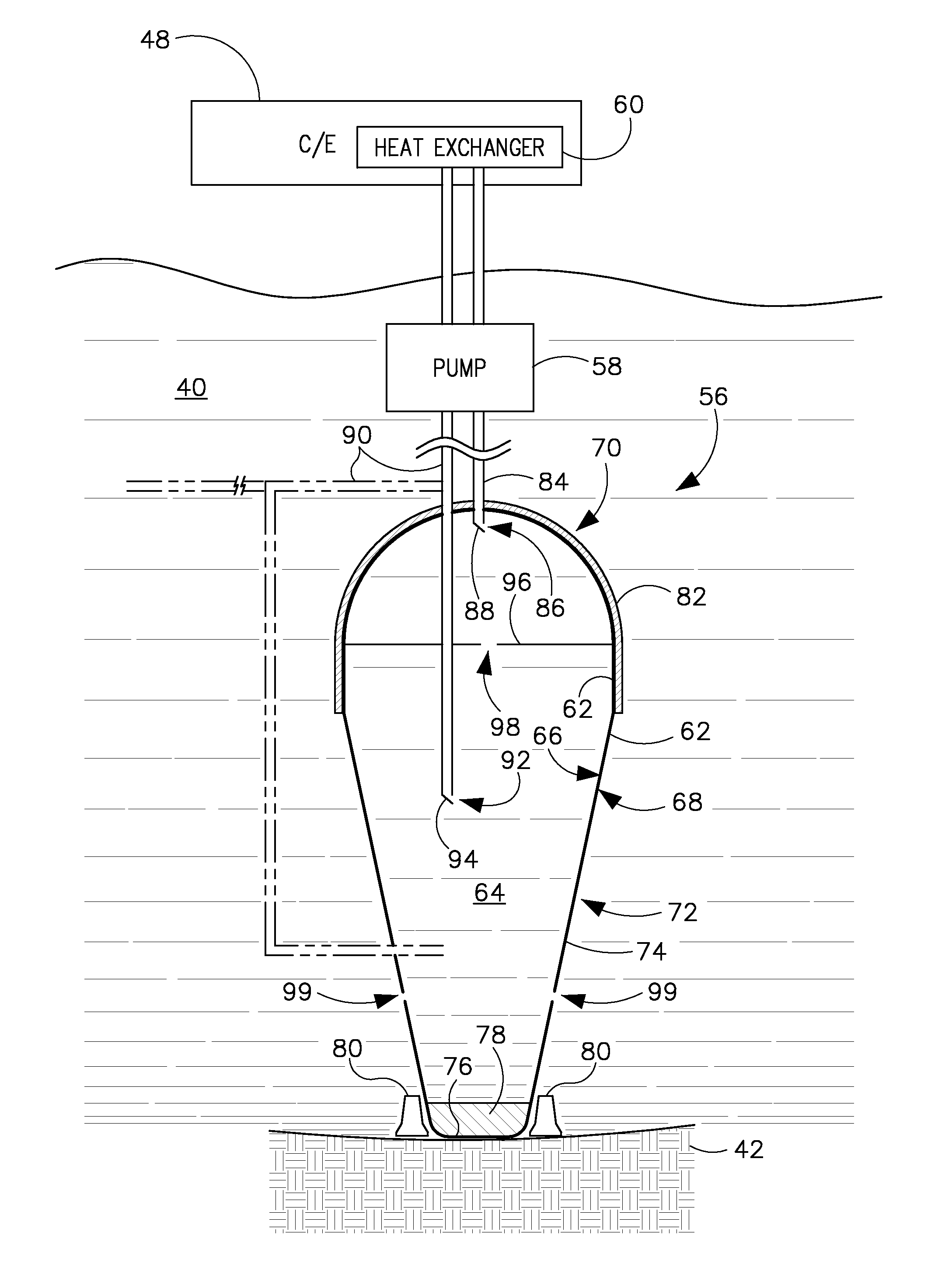
[0035]Embodiments of the invention incorporate a pressure-modifying device with multiple stages, operating with both adiabatic and quasi-isothermal elements. In the compression phase, the device provides several stages of compression to a gas, with the heat of compression being removed after each stage, thus managing the temperature rise in each stage. This heat of compression is then captured in a thermal energy store which can therefore be operated at relatively modest temperatures compared to a fully-adiabatic system with thermal storage. In expansion phase, the same pressure-modifying device operating in reverse, or in other embodiments, a different pressure-modifying device, provides several stages of expansion to the previously compressed gas, with heat being added to the gas before each stage of expansion. In other embodiments heat may be extracted or added to the gas during each stage rather than between stages.

[0036]If the air is compressed from an ambient temperature of 20...


PUM


Abstract

A thermal energy storage system includes a container positioned within a surrounding body of water and comprising a container wall. The wall has an interior surface exposed to and defining an internal volume of the container and has an exterior surface opposite the interior surface and exposed to the surrounding body of water. The internal volume is substantially full of water, and the container is configured to thermally separate water within the internal volume along the interior surface from water of the surrounding body of water along the exterior surface. A thermal source in thermal communication with the water within the internal volume is configured to transfer a thermal potential to the water within the internal volume.

Description

CROSS-REFERENCE TO RELATED APPLICATION[0001]The present application claims priority to U.S. Provisional Application 61 / 364,364 filed Jul. 14, 2010, and to U.S. Provisional Application 61 / 364,368 filed Jul. 14, 2010, the disclosures of which are incorporated herein.BACKGROUND OF THE INVENTION[0002]Embodiments of the invention relate generally to thermal energy storage and, more particularly, to a system and method of storing thermal energy in an underwater storage device.[0003]Renewable energy (RE) sources offer an alternative to conventional power sources in an age of dwindling non-renewable energy sources and high carbon emissions. However, RE sources are often not fully exploited because many forms of renewable energy are not available when the peak demand is present. For instance, RE sources may be most available during undesirable off-peak hours, or may be located in areas that are remote from population centers or locations where power is most needed, having to share the grid d...

Claims


Application Information

Patent Timeline
IPC IPC(8): F24J3/08
CPCF24J3/086Y02E10/34Y02E10/16F24T10/30Y02E10/30F03G7/05Y02E10/10
Inventor VON HERZEN, BRIANFRAZIER, SCOTT RAYMOND
Owner BRIGHT ENERGY STORAGE TECHNOLOGIES LLP
Why Eureka
Try Eureka