Cartridge assembly with ribbon lock

a technology of ribbon lock and cartridge, which is applied in the direction of printing mechanism, inking apparatus, printing, etc., can solve the problems of ink ribbon or media exposed portions becoming loose, ink ribbon being more susceptible to catching on printing components,

Active Publication Date: 2012-02-02
BRADY WORLDWIDE INC
View PDF5 Cites 92 Cited by
  • Summary
  • Abstract
  • Description
  • Claims
  • Application Information

AI Technical Summary

Benefits of technology

The patent text describes a way to prevent ink ribbon from getting bent or getting pulled out of its cartridge during handling. This is done by making the material longer than necessary, so that it doesn't have any slack. This helps to prevent the ink ribbon from getting crumpled or getting pulled out of the cartridge if it gets caught on something.

Problems solved by technology

The patent text is about a problem with printer cartridges. When the cartridges are handled, the media and ink ribbon may become slack, which may cause the ink ribbon to catch on the printer components or get pulled out of the cartridge. The technical problem is to create a media cartridge that can keep the materials taut for handling.

Method used


Image

  • Cartridge assembly with ribbon lock
  • Cartridge assembly with ribbon lock
  • Cartridge assembly with ribbon lock

Examples


Embodiment Construction

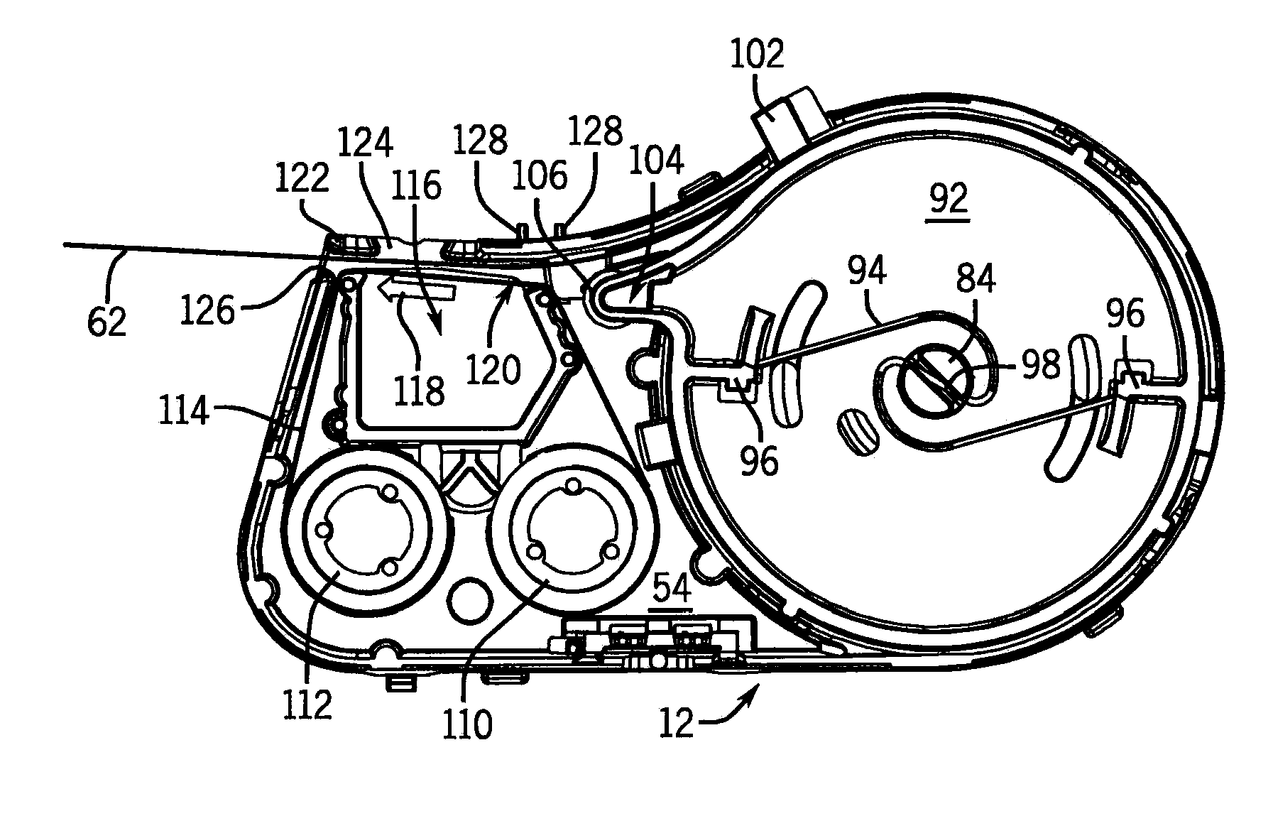
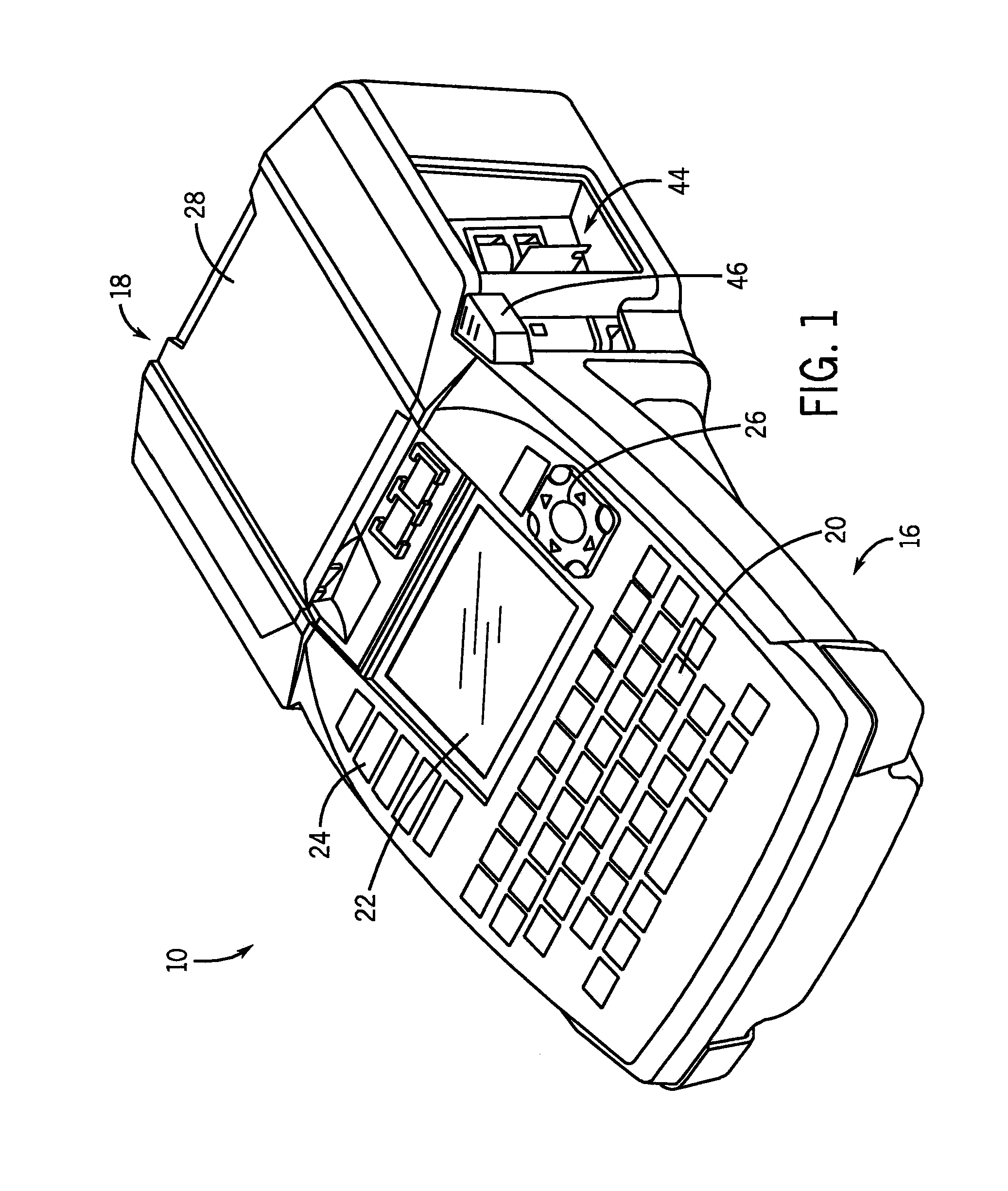
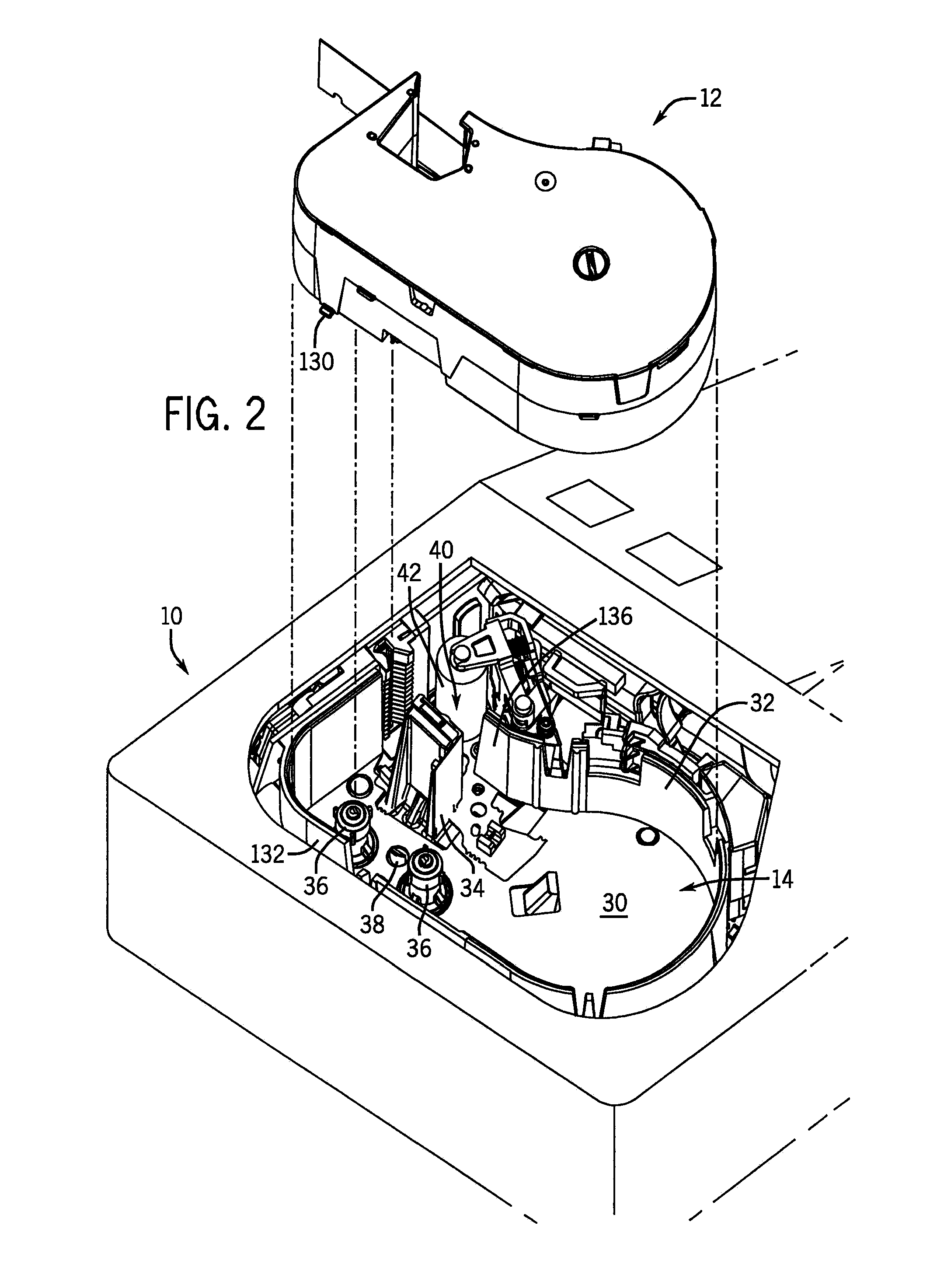
[0048]Referring first to FIG. 1, a printer 10 is shown. The printer 10 is of a type that is a portable handheld printer for use at any of a number of locations and can also be placed on a table top for stationary use. In FIGS. 2 and 3, the printer 10 is shown receiving a media cartridge 12 in a cartridge receptacle 14 of the printer 10. Those having ordinary skill in the art will appreciate that although the printer 10 is shown as being a particular kind of printer, that the features described herein with respect to the media cartridge 12 and the printer 10 are applicable to any number of kinds of cartridge-receiving printers.

[0049]The printer 10 of FIG. 1 includes a body 16 with a head 18 located at one end thereof. The body 16 supports a number of items including a keypad 20 for the entry of data, a display 22 positioned between the keypad 20 and the head 18 of the printer 10, a row of buttons 24 on one lateral side of the display 22, and a navigational keypad 26 on the other late...


PUM


Abstract

A cartridge assembly is disclosed. The cartridge assembly includes a cartridge housing defining an internal chamber. At least one rotatable spool is housed in the internal chamber. In the wall of the cartridge housing, a ribbon lock is formed. The ribbon lock has an engaged position and a disengaged position. In the engaged position, the ribbon lock is biased into engagement with the rotatable spool(s) to inhibit rotation of the rotatable spool(s). In the disengaged position, the ribbon lock is urged away from the rotatable spool(s) to disengage the ribbon lock from the rotatable spool(s) to permit rotation of the spool(s).

Description


Claims


Application Information

Patent Timeline
Owner BRADY WORLDWIDE INC
Why Eureka
Try Eureka