Device for holding cleaning implements

Active Publication Date: 2012-02-23
CHEN JAMES
View PDF20 Cites 1 Cited by
  • Summary
  • Abstract
  • Description
  • Claims
  • Application Information

AI Technical Summary

Benefits of technology

[0005]Thus, what is needed is a means for holding and manipulating such cleaning implements that addresses the aforementioned problems. Such a device would assist a user in cleaning hard-to-reach locations while allowing the cleaning implements to readily be attached and detached, and while providing a degree of translational and rotational stability between the cleaning implement and the holder.
[0006]This application discloses a holder form holding cleaning implements that is economical to produce, of simple construction and capable of mass production, but also capable of providing a holder of cleaning implements that is capable of extending a users reach and that holds the cleaning implements in a stable fashion.

Problems solved by technology

While it is usually is quite easy to apply soap to these cleaning implements, and to apply them in a scrubbing manner by means of the user's hands, it very often is not so easy to get them into positions where they can be placed into contact with the surface to be cleaned, such the back of a bather or the interior of a bottle or jar.
In addition, some cleaning solutions are very hot, or are caustic or the like, in which case the user needs to protect his or her hands.
While this may be done with gloves, the problem of reaching inaccessible places remains.
For example, if the cleaning implement is allowed to slide, or rotate, relative to the surface being cleaned in ways not controllable to the user, then the interactive rubbing action, for example, of the implement relative to the surface may be less than optimal.

Method used


Image

  • Device for holding cleaning implements
  • Device for holding cleaning implements
  • Device for holding cleaning implements

Examples


Embodiment Construction

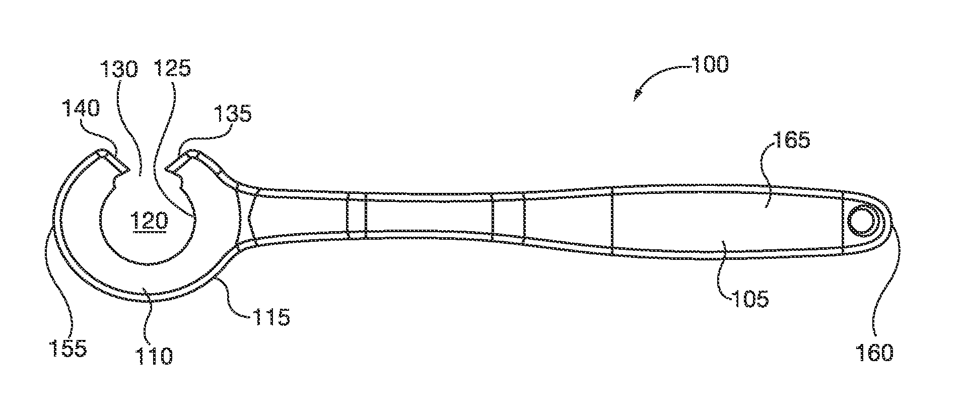
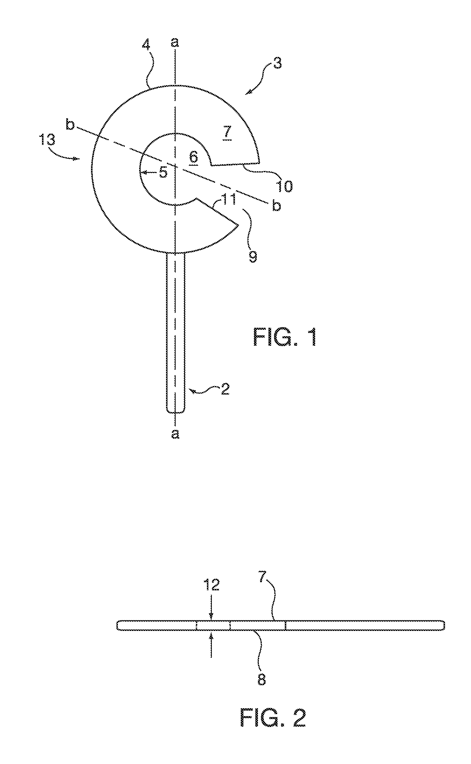
[0023]The following description is of a preferred embodiment of the invention. As shown in FIG. 1, the cleaning implement holding device comprises a handle 2 and a blade 3. Handle 2 can be of any desirable shape, size and length. For example, its cross-section can be circular or otherwise curvilinear, rectangular, or other suitable configuration, and it can be straight or curved. It can be made of any desirable material, such as wood, metal or plastic. Blade 3 has an outer blade edge 4 outlining its periphery, and an inner blade edge 5, which defines a central opening 6. Opening 6 may be any desirable shape, but preferably is circular. Blade 3 may be of any suitable shape, and is shown here in a preferred circular shape, and it may be stiff or flexible. Blade 3 has a first face 7 and a second face 8. A channel 9 extends radially between outer edge 4 and inner edge 5, bounded by a first channel edge 10 and a second channel edge 11. Channel 9 can be of constant width along its length,...


PUM

PropertyMeasurementUnit
Thicknessaaaaaaaaaa
Angleaaaaaaaaaa
Flexibilityaaaaaaaaaa

Abstract

A device for holding and manipulating compressible cleaning implements is disclosed wherein the cleaning implements may be made from a compressible material and may have a compressible portion. The device may include a handle. A blade may be attached to the handle. An outer blade edge may surround the blade. An opening through the blade may be defined by an inner blade edge. A channel may pass through the blade and may extend from the inner blade edge to the outer blade edge, and may be defined by a first channel edge and a second channel edge. The compressible portion of the cleaning implement may be passed through the channel into the opening and may be held in the opening by engagement with the inner blade edge. Each of the first and second channel edges may respectively define first and second circumferentially directed points configured to poke into the compressible material.

Description

CROSS-REFERENCE TO RELATED APPLICATION[0001]This application claims the benefit of the filing date under 35 USC 119(e) of the filing date of U.S. Provisional application Ser. No. 12 / 543,702, filed Aug. 19, 2009, the contents of which are incorporated herein by reference.FIELD OF THE INVENTION[0002]This application relates generally to cleaning implements, and more specifically to a device for holding cleaning implements such as those used in bathing, dishwashing, and other cleaning tasks which includes one or more features to minimize relative movement between a cleaning implement and the holder.BACKGROUND AND SUMMARY[0003]Cleaning implements such as sponges, mesh balls, applicators, and similar flexible compressible porous and permeable materials commonly are used to clean the skin of people and animals, as well as to clean inanimate objects. While it is usually is quite easy to apply soap to these cleaning implements, and to apply them in a scrubbing manner by means of the user's ...

Claims


Application Information

Patent Timeline
IPC IPC(8): A46B5/02
CPCA46B5/021A46B5/02A46B9/005A46B7/04
Inventor CHEN, JAMES
Owner CHEN JAMES
Why Eureka
Try Eureka