Method of installing exhaust tube

Active Publication Date: 2016-02-25
NORITZ CORP
View PDF0 Cites 6 Cited by
  • Summary
  • Abstract
  • Description
  • Claims
  • Application Information

AI Technical Summary

Benefits of technology

[0007]The present invention has been made in light of the above-described problems. An object of the present invention is to provide a method of installing an exhaust tube, by whi

Problems solved by technology

When a new exhaust tube is inserted into the already-placed exhaust pipe from inside of a building, the tip end of the exhaust tube gets caught in the inner circumferential surface of the exhaust pipe, which causes a problem that it becomes difficult to push the exhaust tube in.
Furthermore, the tip end of the exhaust tube gets caught in the inner circumferential surface of the exhaust pipe,

Method used


Image

  • Method of installing exhaust tube
  • Method of installing exhaust tube
  • Method of installing exhaust tube

Examples


Example

[0033]Embodiments of the present invention will be hereinafter described with reference to the drawings.

[0034]An exhaust structure for a combustion apparatus in one embodiment of the present invention will be first described.

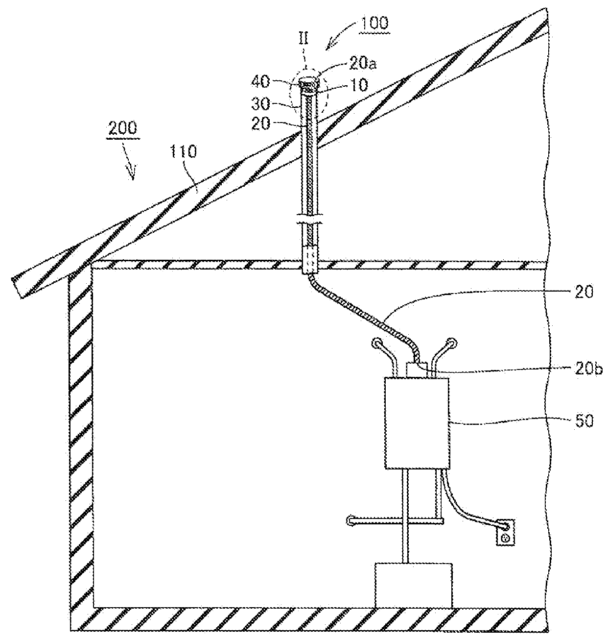
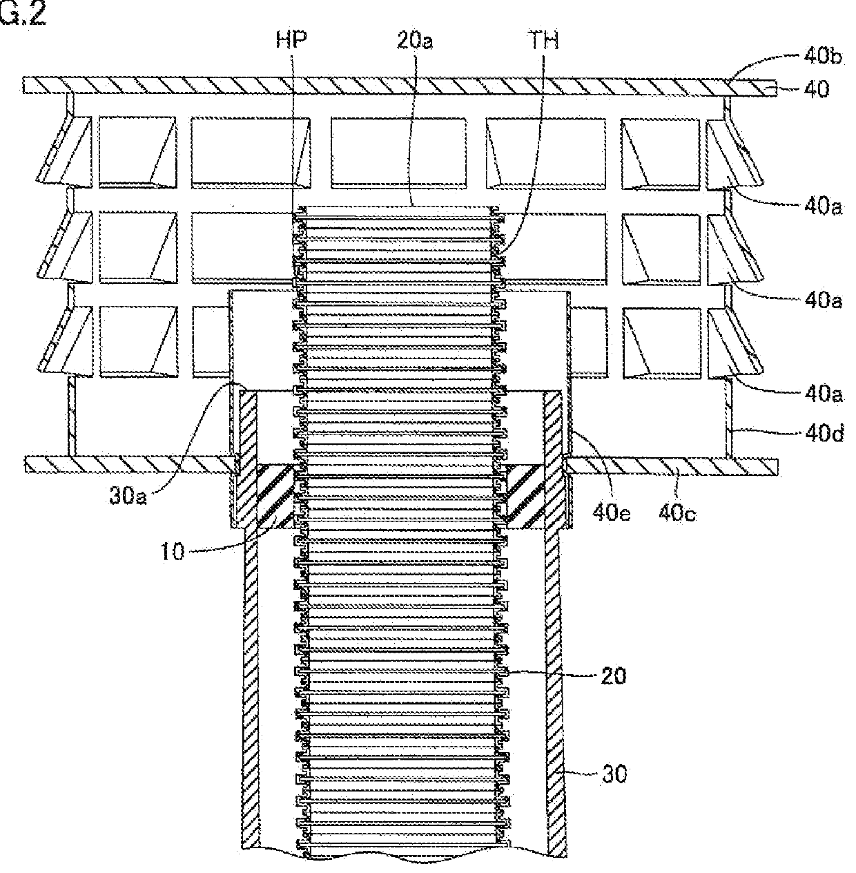
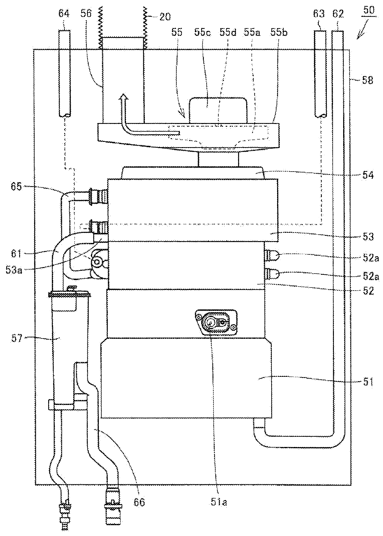
[0035]Referring to FIGS. 1 to 3, an exhaust structure for combustion apparatus 100 in the present embodiment mainly has an exhaust adapter 10, an exhaust tube 20, an exhaust pipe 30, an exhaust terminal 40, and a combustion apparatus 50. This exhaust structure for combustion apparatus 100 serves to emit combustion gas produced in combustion apparatus 50 to the outside of a building 200.

[0036]Combustion apparatus 50 is placed inside building 200. This combustion apparatus 50 serves as a water heater that heats warm water and water, for example, with combustion gas, and may be a heating apparatus or the like that warms up the inside of the building with combustion gas. Furthermore, in the case where a water heater is used as combustion apparatus 50, this water hea...


PUM

PropertyMeasurementUnit
Frictionaaaaaaaaaa

Abstract

A method of installing an exhaust tube is implemented by inserting an exhaust tube into an exhaust pipe that leads from inside of a building to outside thereof. A support portion of an insertion jig is introduced into a through hole from a side of one end portion of the exhaust tube, and a projection of the support portion is engaged with a recess of the exhaust tube, so that the insertion jig is fixed to the exhaust tube. An end of the exhaust tube on the side of the one end portion having the insertion jig fixed thereto is inserted into the exhaust pipe, and the exhaust tube is pushed from inside of the building to outside thereof.

Description

BACKGROUND OF THE INVENTION[0001]1. Field of the Invention[0002]The present invention relates to a method of installing an exhaust tube.[0003]2. Description of the Background Art[0004]In markets, there are locations where an exhaust pipe (a B vent) already placed in a building cannot be removed from a point of view of maintaining appearance of buildings. At such a location, a combustion apparatus can be replaced by inserting a new exhaust tube (a flexible exhaust tube) into the exhaust pipe and an exhaust terminal (a rain cap) which have already been placed.[0005]Although not a technique related to an exhaust pipe of a combustion apparatus, a method of inserting a corrugated tube made of resin into a pipe such as a gas pipe and a water pipe is disclosed, for example, in Japanese Patent Laying-Open No. 2002-188755. This document discloses a traction jig for a corrugated tube.[0006]When a new exhaust tube is inserted into the already-placed exhaust pipe from inside of a building, the ...

Claims


Application Information

Patent Timeline
IPC IPC(8): F23J13/04F23J13/02F23J13/06
CPCF23J13/025F23J13/04F23J13/06F16L11/15F16L55/1141F16L55/115B21D39/00F16L2101/20F16L55/11F23L17/02F23J2213/101F23J2213/203F23J2213/50F23J2900/13021F16L55/165
Inventor SUGATANI, MASAKIMATSUNAGA, HIRONAO
Owner NORITZ CORP
Why Eureka
Try Eureka