System and method for paralleling electrical power generators

Active Publication Date: 2012-03-01
KOHLER CO
View PDF7 Cites 53 Cited by
  • Summary
  • Abstract
  • Description
  • Claims
  • Application Information

AI Technical Summary

Benefits of technology

[0021]It should be appreciated that this system avoids the need for many equipment parts previously required to achieve the paralleling of multip

Problems solved by technology

Furthermore, large generators present difficulties in shipping and installation complexity.
Traditional generator paralleling techniques have been quite complex, often requiring several additional pieces of equipment to achieve the needed functions.
Moreover, prior art paralleling systems can require significant time to synchronize the operation of the multiple generators once a power need is appreciated.
In addition, traditional systems are not well suited to

Method used


Image

  • System and method for paralleling electrical power generators
  • System and method for paralleling electrical power generators
  • System and method for paralleling electrical power generators

Examples


Embodiment Construction

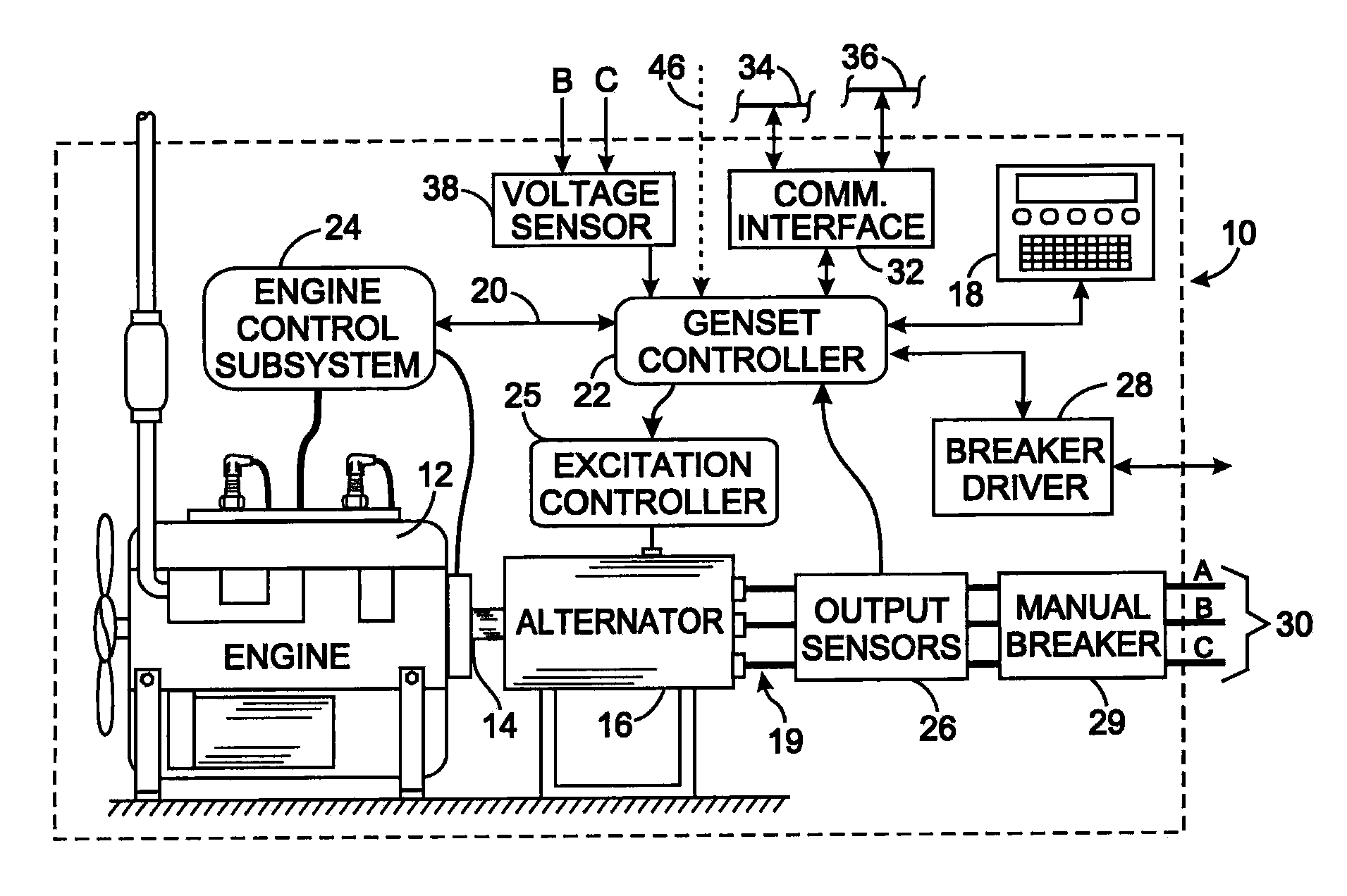
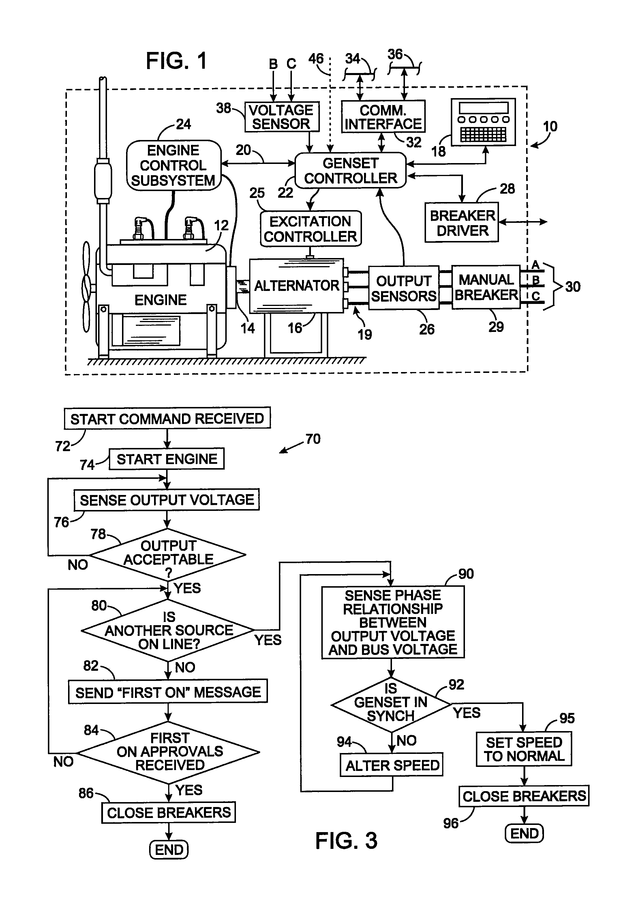
[0029]With initial reference to FIG. 1, a generator 10, sometimes called an engine generator set or simply a genset, comprises an prime mover, such as an internal combustion engine 12, coupled by a shaft 14 to an electrical alternator 16. In one application, the generator 10 provides back-up electrical power to a building in the event that power from an electric utility company is interrupted. Such interruption is detected by an external device that sends a signal to a genset controller 22 which responds by sending a start command via a communication bus 20 to an engine control subsystem 24. The communication bus 20 may conform to the Computer Area Network (CAN) J-1939 standard promulgated by SAE International, however, other communication bus protocols may be used. The genset controller 22 and the engine control subsystem 24 respectively control operation of the alternator 16 and the internal combustion engine 12.

[0030]In another application, the generator 10 produces electrical po...


PUM


Abstract

A plurality of generators can be connected in parallel to a common electrical bus. Each generator has a controller that regulates the voltage and frequency of the electricity being produced. Before a given generator connects to the electrical bus, its controller senses whether electricity is present on the bus and if not, the connection is made. Otherwise, the controller synchronizes the electricity being produced to the electricity is present on the bus before the connection occurs. The controller in each generator may also implement a load sharing function which ensures that the plurality of generators equitably share in providing the total amount of power demanded by the loads. The load sharing can be accomplished by controlling the generators to operate a substantially identical percentages of their individual maximum power generation capacity.

Description

CROSS-REFERENCE TO RELATED APPLICATIONS[0001]Not ApplicableStatement Regarding Federally Sponsored Research or Development[0002]Not ApplicableBACKGROUND OF THE INVENTION[0003]1. Field of the Invention[0004]The present invention relates to systems that use a plurality of electric power generators working together; and more particularly, to systems which operate multiple electric power generators in parallel to provide the power in a more efficient and flexible manner.[0005]2. Description of the Related Art[0006]Standby generators provide electrical power when power is unavailable from an electric utility company (e.g. during weather disturbances) or to provide power at a remote location where utility company power is not available. One type of standby electric generator comprises an internal combustion engine driving an electrical alternator that produces alternating electricity. Other types of standby electric generators include photovoltaic arrays and wind turbine generators.[0007]...

Claims


Application Information

Patent Timeline
IPC IPC(8): H02J3/42
CPCH02J3/42
Inventor DORN, DOUGLAS W.FRAMPTON, ISAAC S.
Owner KOHLER CO
Why Eureka
Try Eureka