Load bearing assembly

Inactive Publication Date: 2012-10-30
BP EXPLORATION OPERATING CO LTD
View PDF15 Cites 2 Cited by
  • Summary
  • Abstract
  • Description
  • Claims
  • Application Information

AI Technical Summary

Benefits of technology

[0021]The present invention has the advantage that the assembly can be used with a conventional well head assembly. The load bearing assembly can be connected to the well head in exactly the same way as is widely used when currently deploying pump assemblies into well bores on the end of jointed tubing strings.
[0022]Further, no new, unproven method of routing the electrical cable from the well to the surface is required. The electrical cable can be routed from the well to the surface using a standard, industry-trusted penetrator or any other known fluid to air connector already used. Accordingly, the user can be reassured that the electrical cable need not extend through the Christmas tree, and can be confident of the integrity of the seal around the electrical cable.
[0023]In addition, the need for very many different types o

Problems solved by technology

As failure of the fluid to air connector (7) would compromise the ability of the well head to contain well pressure, it is a safety critical component.
Conventional methods of installing pump assemblies on jointed production tubing in wells requires the use of expensive workover rigs to remove and re-install the production tubing when maintenance or repair of the pump assembly is required.
This process is also time consuming.
However, the substantially rigid outer metal jacket is not intended to support an applied axial load, nor is it capable of so doing.
However, this method is rarely used because of its limited advantages over conventional jointed tubing.
In all cases, the electrical conductor and in some cases the tubing encapsulation is

Method used


Image

  • Load bearing assembly
  • Load bearing assembly
  • Load bearing assembly

Examples


Embodiment Construction

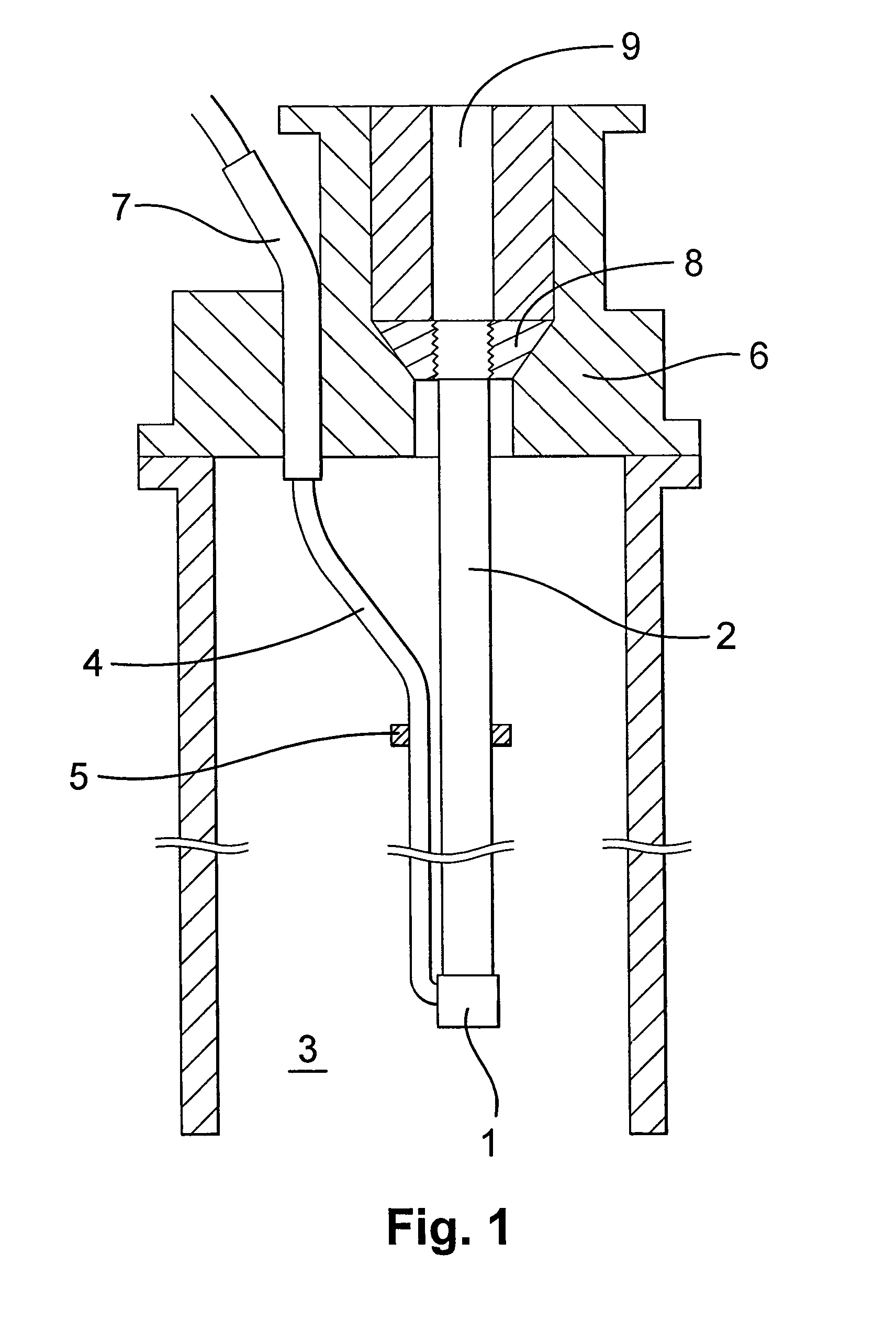
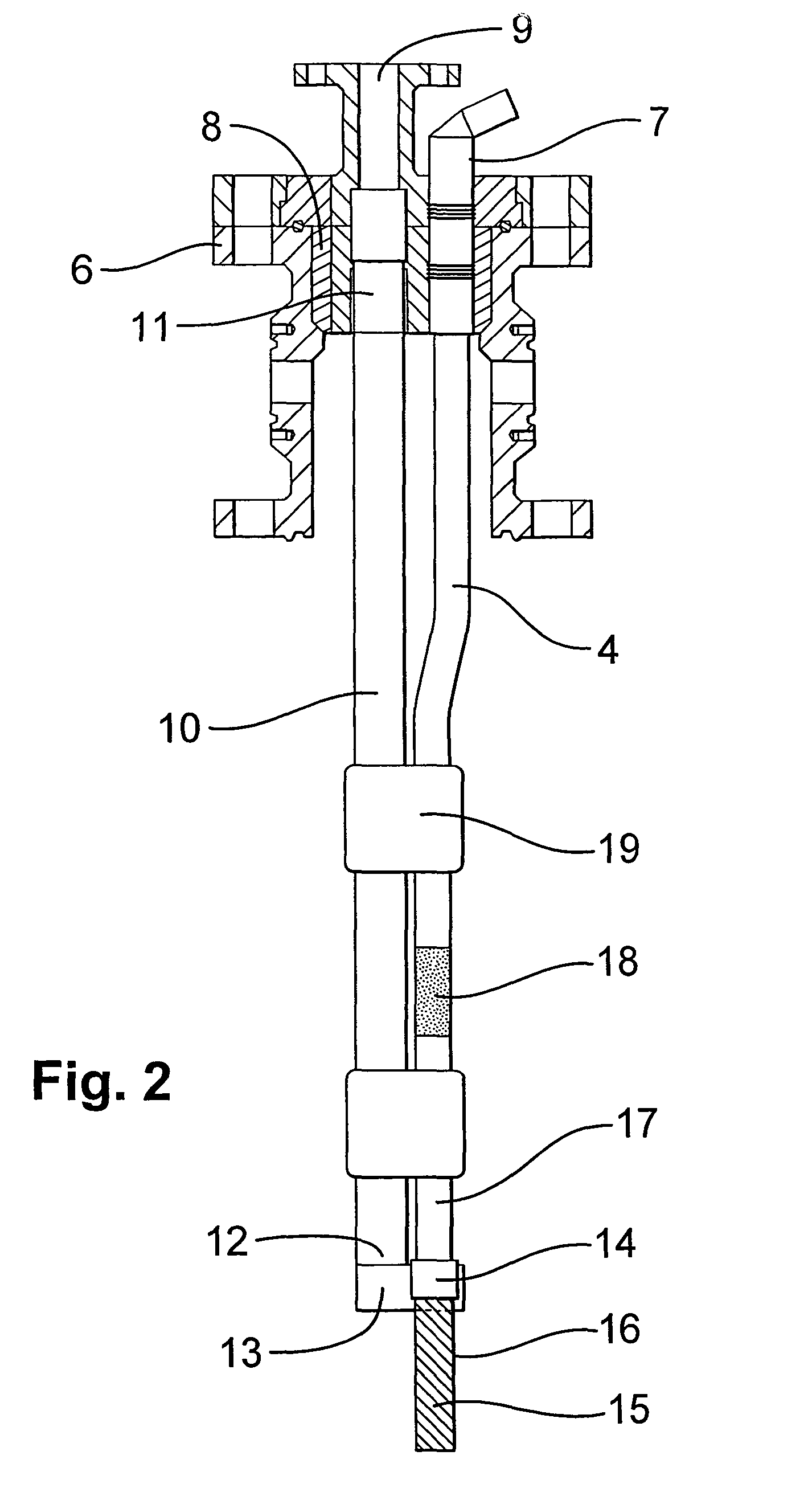
[0044]FIG. 2 shows a well head (6) from which the load bearing assembly of the present invention is suspended. The well head is of the conventional type used widely to suspend a jointed production tubing string in a well, and has a connector (8) to which the top end of the production tubing string connects, a passage (9) through which well fluids can flow and a penetrator (7) through which an electrical conductor (4) extends, the penetrator sealing around the electrical conductor and providing a seal between the well environment and the external environment. The penetrator is manufactured with the electrical conductor (4) extending there-through so that its lowest end can be spliced in situ onto an electrical conductor for powering down hole equipment.

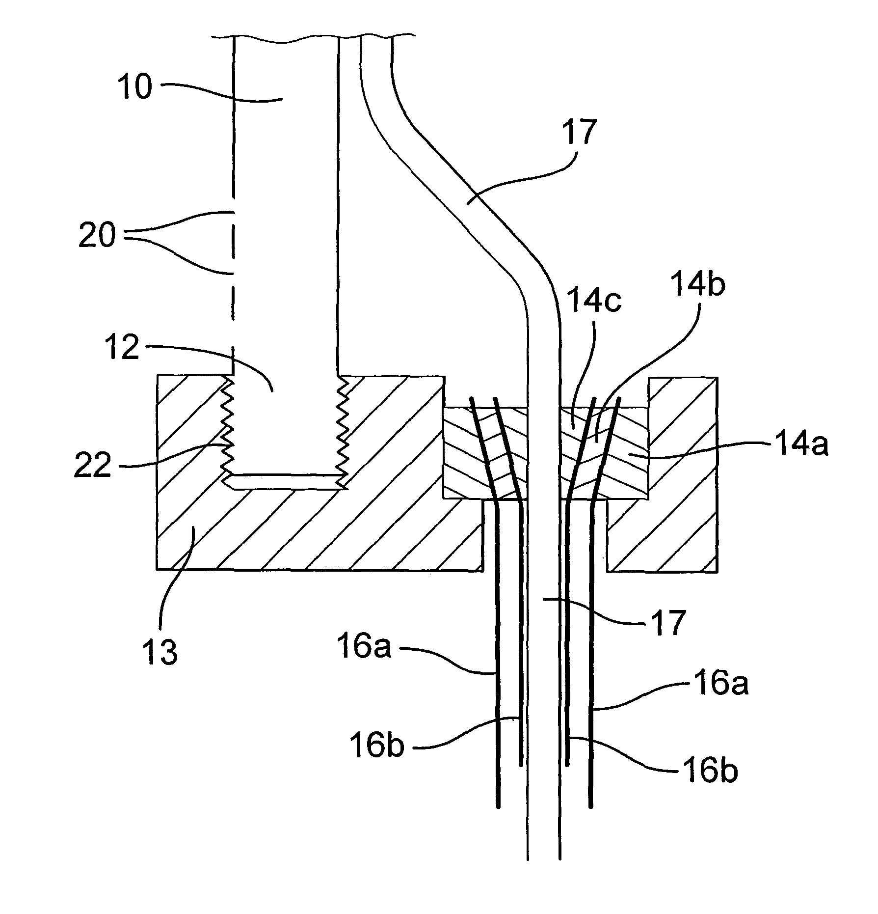
[0045]The assembly of the present invention comprises a first section in the form of a portion of tubing (10) having a first end (11) and an opposing second end (12). The first end (11) is connected to the well head (6) using the well ...


PUM


Abstract

Load bearing assembly for suspending a load from a wellhead assembly, having a connector for suspending jointed production tubing therefrom and a fluid-to-air connector seals around an electrical conductor extending therethrough. The assembly has a jointed production tubing section with a first connector for connecting the tubing to the wellhead assembly connector. The assembly has a second connector for connecting the jointed production tubing section to a load bearing part of an electrical conduction section of the assembly. The load bearing part suspends the weight of the electrical conduction section and a load in a well from the second connector. The electrical conduction section includes an electrical conductor part for supplying electrical power to the load. The electrical conductor part is connected to an electrical cable which extends outside and along the jointed production tubing section away from the second connector and towards the well head in use.

Description

[0001]This application is the U.S. national phase of International Application No. PCT / GB2009 / 001763, filed 17 Jul. 2009, which designated the U.S., and claims priority to EP Application No. 08252555.1, filed 28 Jul. 2008, the entire contents of each of which are hereby incorporated by reference.[0002]This invention relates to a load bearing assembly for suspending a load in a well, and particularly to an assembly for suspending a load from an electro-mechanical cable or a tubing-encapsulated power cable. An electro-mechanical cable is a cable which can conduct electricity as well as support a load and its own weight. Typically, electro-mechanical cables comprise an electrically conductive core surrounded by a spiral wound outer sheath capable of supporting both the weight of the cable (core and sheath) and a load supported at the lower end of the cable. Tubing-encapsulated power cable includes coiled tubing in which a separate power cable extends through a length of spoolable tubin...

Claims


Application Information

Patent Timeline
IPC IPC(8): E21B33/04
CPCE21B33/03H02G15/013E21B43/128E21B33/0407H02G15/007
Inventor DENNY, MARK JOSEPH
Owner BP EXPLORATION OPERATING CO LTD
Why Eureka
Try Eureka