

Mechanical arrangement for use within galvanically-isolated, low-profile micro-inverters for solar power installations
- Summary
- Abstract
- Description
- Claims
- Application Information
AI Technical Summary
Benefits of technology
Problems solved by technology
Method used
Image

Examples
Embodiment Construction
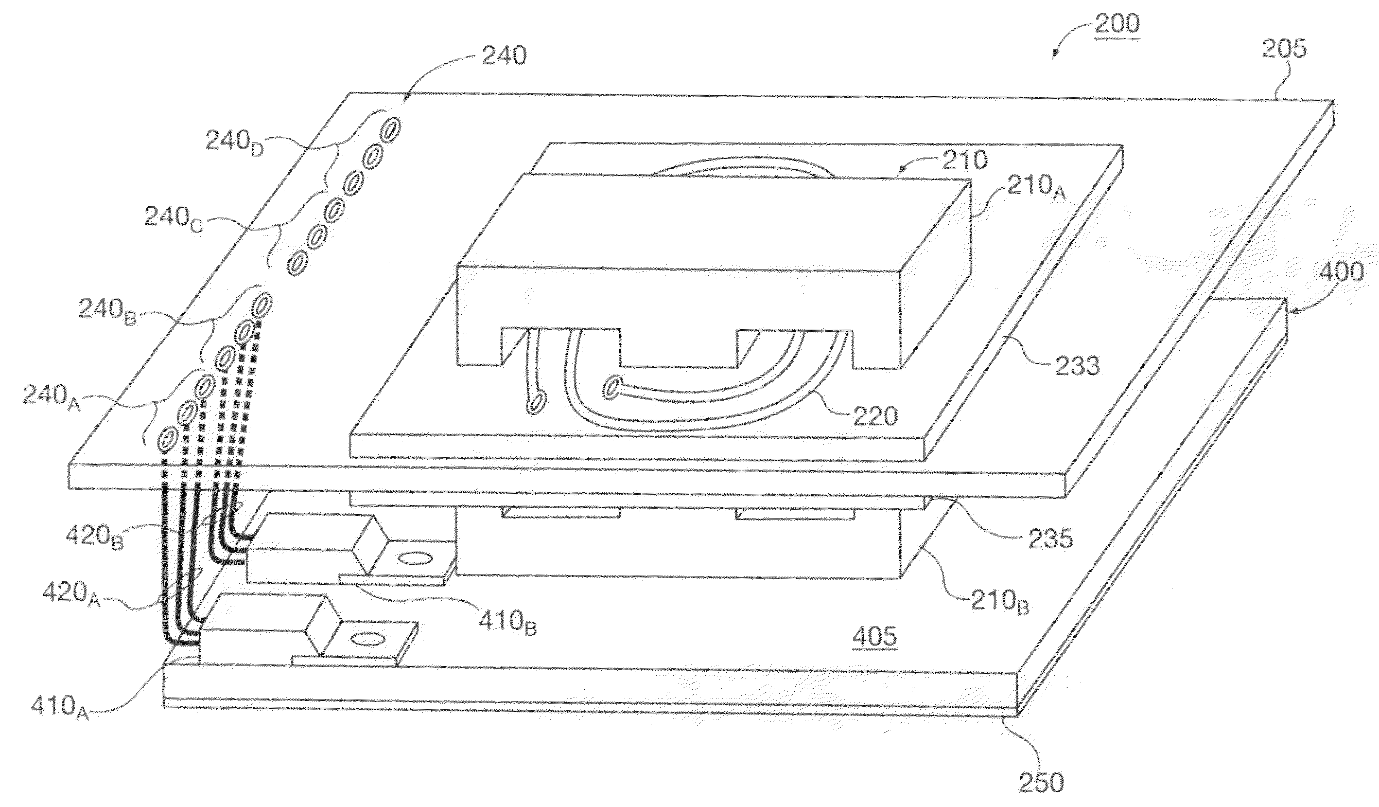
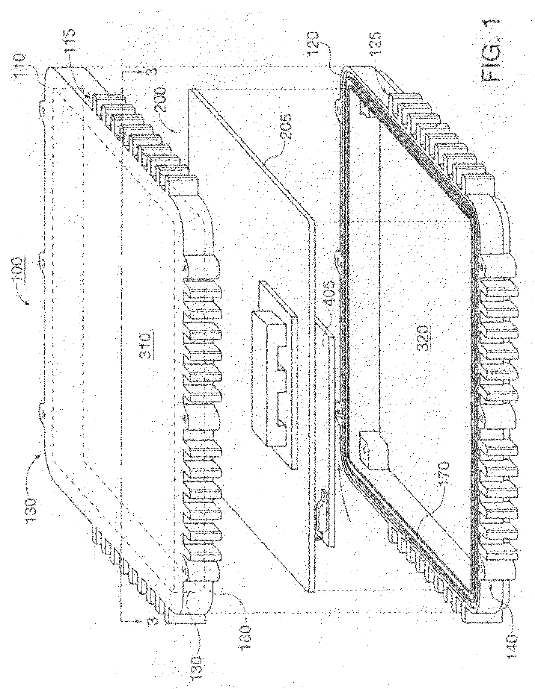
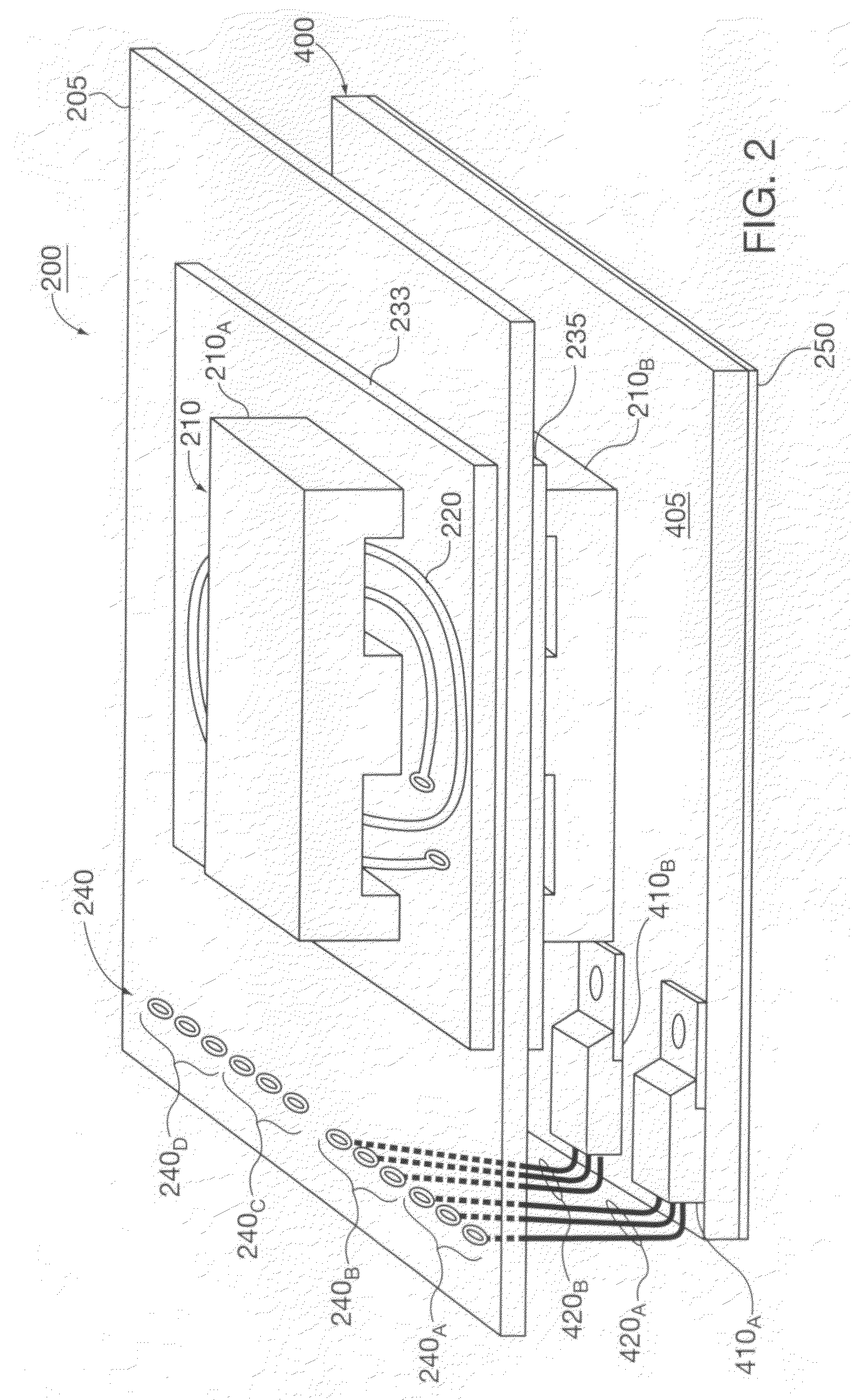
[0023]After considering the following description, those skilled in the art will clearly realize that the teachings of our present invention could be utilized in a wide range of electronic applications that could beneficially employ a planar transformer but are constrained to house the attendant circuitry, including the transformer, in a low-profile enclosure and solely rely on passive cooling. For ease of discussion, we will discuss our invention in the context of its use in implementing low-profile micro-inverters, for solar installations, that will convert a direct current output supplied by a photovoltaic panel into alternating current output line power.
[0024]In such installations, a micro-inverter is generally mounted directly behind a solar panel racking system which, due to available space, limits the thickness of its enclosure to no more than 1.25″ (approximately 3.2 cm), thus necessitating a low-profile enclosure. Further, the micro-inverter should galvanically isolate its ...
PUM
 Abstract
Description
Claims
Application Information