Light engine

Inactive Publication Date: 2014-09-18
ABL IP HLDG
View PDF6 Cites 3 Cited by
  • Summary
  • Abstract
  • Description
  • Claims
  • Application Information

AI Technical Summary

Benefits of technology

[0005]In certain embodiments there is provided a light engine with a heat sink having a curved recessed cavity that receives a flexed PCB bearing a plurality of LEDs. Once released, the elastic PCB has a tendency to attempt to return to its flat state. Flanges or other suitable mechanisms along the ends of the cavity, however, restrain the edges of the PCB and prevent the PCB from returning to its flat state. In this way, the PCB is securely retained with

Problems solved by technology

Flanges or other suitable mechanisms along the ends of the cavity, however, restrain the edges of the PCB and prevent the PCB from returning to its flat state.
Moreover, the inab

Method used


Image

  • Light engine
  • Light engine
  • Light engine

Examples


Example

DETAILED DESCRIPTION OF THE DRAWINGS

[0011]The subject matter of embodiments of the present invention is described here with specificity to meet statutory requirements, but this description is not necessarily intended to limit the scope of the claims. The claimed subject matter may be embodied in other ways, may include different elements or steps, and may be used in conjunction with other existing or future technologies. This description should not be interpreted as implying any particular order or arrangement among or between various steps or elements except when the order of individual steps or arrangement of elements is explicitly described.

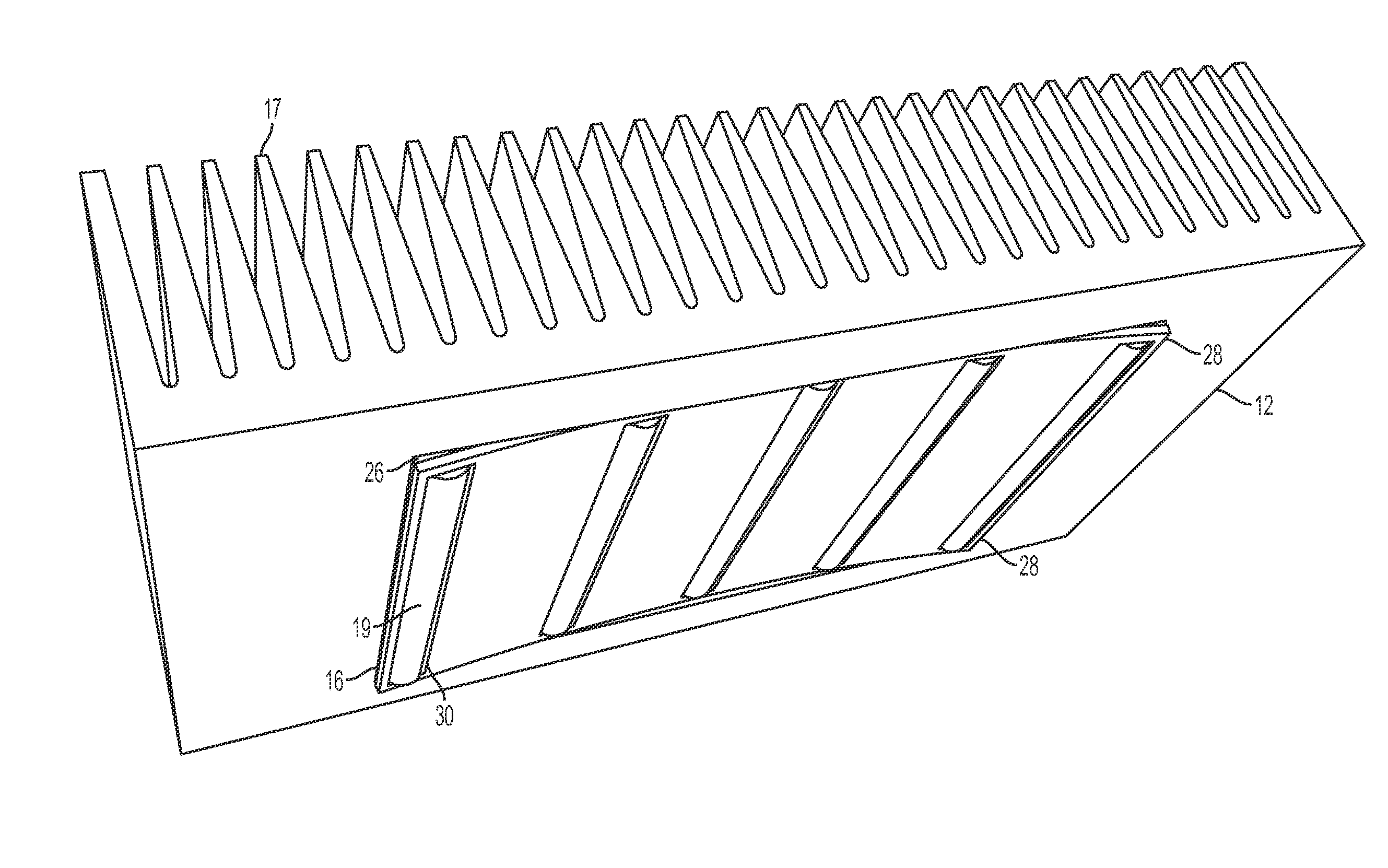
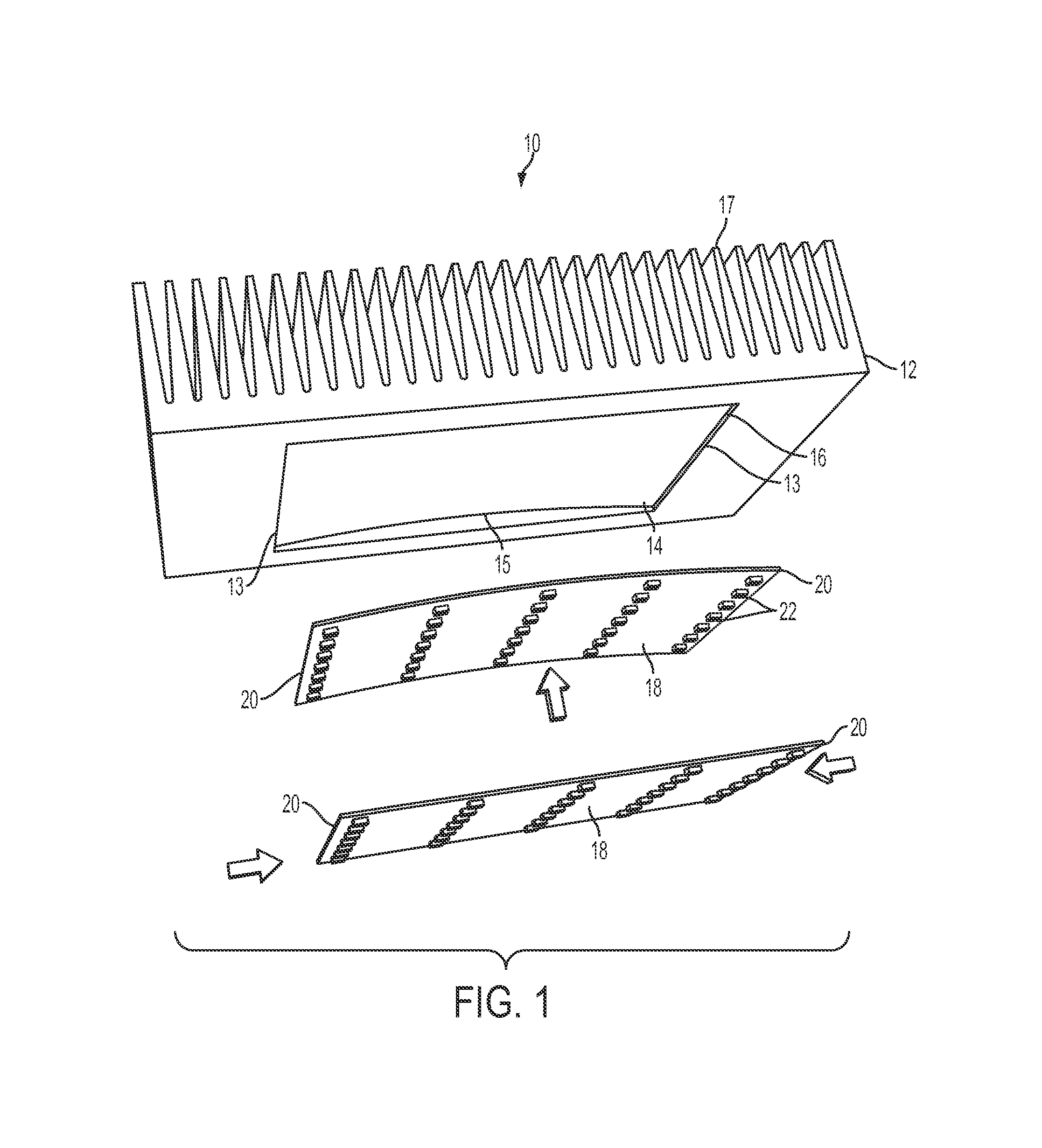
[0012]FIG. 1 illustrates various components of a light engine 10 according to one embodiment of the invention. Light engine 10 comprises a heat sink 12. The side of heat sink 12 that faces the area to be lit includes a recessed cavity 14 that is sized and shaped to receive a printed circuit board (PCB) 18 having a plurality of LEDs 22 mounted ...


PUM


Abstract

A light engine with a heat sink having a curved recessed cavity that receives a flexed or cupped PCB bearing a plurality of LEDs. Once situated within the cavity and released, the PCB has a tendency to return to its flat state, but flanges or other suitable mechanisms at the ends of the cavity restrain the edges of the PCB and prevent the PCB from returning to its flat state. In this way, the PCB is securely retained within and biased against the cavity by its own forces. As the PCB heats, the PCB expands, further biasing the PCB against the cavity of the heat sink and increasing the thermal conductivity between the two components.

Description

FIELD OF THE INVENTION[0001]Embodiments of the invention generally relate to light engines comprising flexed printed circuit boards and methods pertaining to the same.BACKGROUND OF THE INVENTION[0002]Conventional light fixtures use light emitting diodes (“LEDs”) or other suitable light sources. Because LEDs and other light sources give off thermal energy, luminaire housings with heat sinks are sometimes incorporated into the light fixture to facilitate heat dissipation from the light sources. Such heat dissipation can result both from conduction of heat from the light sources via the heat sink material as well as convection of heat from the heat sink to the air circulating through and around the heat sink.[0003]When LEDs are used as the light source, a printed circuit board (“PCB”) is typically populated with LEDs that are wired to the PCB. During assembly of the light fixture, the PCB (with LEDs mounted thereon) is typically fastened to the heat sink using either multiple screws or...

Claims


Application Information

Patent Timeline
IPC IPC(8): H01L33/64
CPCH01L33/644H01L25/0753H01L2924/0002H05K1/021H05K2201/10106H05K2201/10598H05K2201/209H05K2203/302F21V19/004F21Y2105/10F21Y2115/10H01L2924/00
Inventor MCCANLESS, FORREST STARNES
Owner ABL IP HLDG
Why Eureka
Try Eureka