Organic el light-emitting device and method for manufacturing the organic el light-emitting device

Inactive Publication Date: 2011-03-03
YAMAGATA PROMOTIONAL ORG FOR INDAL TECH +1
View PDF11 Cites 24 Cited by
  • Summary
  • Abstract
  • Description
  • Claims
  • Application Information

AI Technical Summary

Benefits of technology

[0035]According to the grease layer or the gel layer containing the oligomer or the polymer having organosiloxane or fluorinated polyether as a skeleton, the thermal conductivity can be increased compared with the constitution disclosed in the Japanese Patent Application Laid-Open Nos. 2000-357587, 2001-217071, and 2003-173868, in which a gas or a liquid is filled and sealed in between the element formation substrate, on which the organic EL element is formed, and the sealing substrate. Accordingly, the speed of heat dissipation of the organic EL light-emitting device can be increased through the grease layer or the gel layer, and, at the same time, the entire temperature can be uniformly maintained.
[0036]According to the above constitution, even in the organic EL light-emitting device having a relatively large light-emitting area, the operational temperature can be rendered uniform, whereby the brightness unevenness in the organic EL light-emitting panel generated due to the influence of the characteristics of the organic EL element and the influence of the heat generation of the organic EL element can be effectively prevented.
[0037]The grease layer or the gel layer serves for moistureproof of th

Problems solved by technology

Thus, even when the entire light-emitting panel is driven by constant current, the electric current value near the power-feeding part is higher than that in the portion distant from the power-feeding part, whereby the portion near the power-feeding part is more brightly illuminated, leading to the occurrence of unevenness of the light emission brightness.
The temperature of the organic EL element is increased by the heat generation to facilitate the flow of current, and the current is applied, in a

Method used


Image

  • Organic el light-emitting device and method for manufacturing the organic el light-emitting device
  • Organic el light-emitting device and method for manufacturing the organic el light-emitting device
  • Organic el light-emitting device and method for manufacturing the organic el light-emitting device

Examples


Embodiment Construction

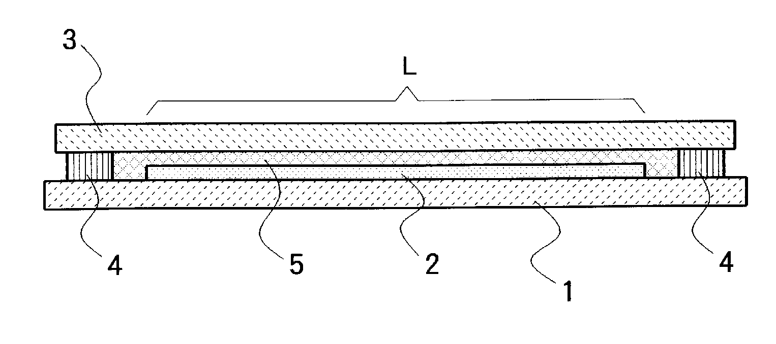
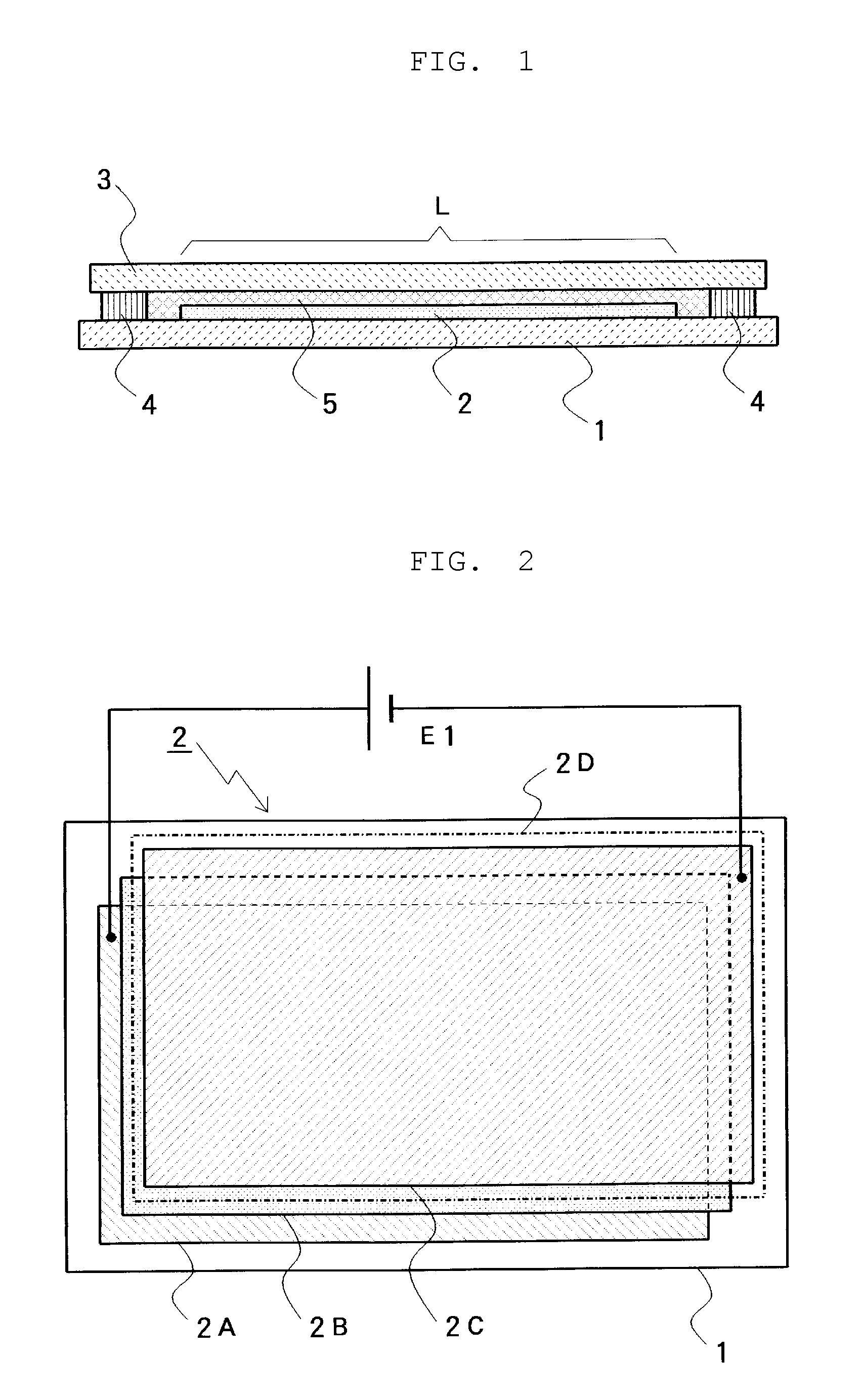
[0067]Hereinafter, an organic EL light-emitting device according to this invention will be described based on embodiments shown in the drawings. FIG. 1 is a schematic view (cross-sectional view) of an example of a basic structure of the organic EL light-emitting device according to this invention. An element formation substrate 1 is formed of a transparent material such as glass and formed into, for example, a rectangular shape. The element formation substrate 1 has on its one side (the upper surface shown in FIG. 1) an organic EL element 2 stacked thereon.

[0068]A plate-shaped sealing substrate 3, formed into a rectangular shape like the element formation substrate 1, is disposed so as to face the surface of the element formation substrate 1, on which the organic EL element 2 is stacked. The element formation substrate 1 and the sealing substrate 3 are sealed at the peripheral edge portion of the four sides with a sealing portion 4 through an adhesive. A space is provided between th...


PUM

PropertyMeasurementUnit
Fractionaaaaaaaaaa
Thicknessaaaaaaaaaa
Weight ratioaaaaaaaaaa

Abstract

This invention provides an organic EL light-emitting device, which can prevent the occurrence of brightness unevenness due to resistance of a transparent electrode, in a large surface light-emitting panel of an organic EL element.
The organic EL light-emitting device includes an element formation substrate 1, on which an organic EL element 2 including an organic light-emitting layer is stacked, and a sealing substrate 3 for sealing the organic EL element so as to accommodate the organic EL element between the element formation substrate and the sealing substrate. A sealing portion 4 formed of an adhesive is formed in the peripheral edge portion between the element formation substrate 1 and the sealing substrate 3, and a grease layer 5 or a gel layer 5 is accommodated in between the element formation substrate, on which the organic EL element surrounded by the sealing portion is formed, and the plate-shaped sealing substrate so as to adhere to the element formation substrate and the sealing substrate. The grease layer 5 or the gel layer 5 contains an oligomer or a polymer having organosiloxane bond(—R2SiO—) or fluorinated polyether (—CF2CFYO—) as a skeleton.

Description

FIELD OF THE INVENTION[0001]This invention relates to an organic EL (electroluminescence) light-emitting device using an organic EL element as a light-emitting source and a method for manufacturing the organic EL light-emitting device.DESCRIPTION OF THE RELATED ART[0002]An organic EL element is driven by a DC power supply with a low voltage to thereby provide a high light-emitting efficiency, and can be reduced in weight and thickness, whereby the organic EL element is used in a flat panel display (FPD) in some portable apparatuses. In addition, there is provided one in which the organic EL element as a surface light-emitting source is used as, for example, a backlight for a liquid crystal display element.[0003]Meanwhile, the organic EL element can provide various light emission colors depending on the selection of a material used for a light-emitting layer. Accordingly, one or a combination of two or more kinds of the light emission colors can provide an arbitrary light emission co...

Claims


Application Information

Patent Timeline
IPC IPC(8): B32B3/02B32B37/12
CPCH01L51/529H05B33/04H05B33/10Y10T428/239H01L51/5237H10K50/846H10K50/87H10K50/8426H10K50/844
Inventor SUZUKI, JOJIKAJIKAWA, FUJIOKAWASHIMA, YASUKINAKAI, SHIGEYUKI
Owner YAMAGATA PROMOTIONAL ORG FOR INDAL TECH
Why Eureka
Try Eureka