Recording device and recording and cutting control method

Inactive Publication Date: 2012-03-15
SEIKO EPSON CORP
View PDF5 Cites 6 Cited by
  • Summary
  • Abstract
  • Description
  • Claims
  • Application Information

AI Technical Summary

Benefits of technology

[0008]An advantage of some aspects of the invention is that the amount of cutting waste gen

Problems solved by technology

Here, the plurality of images are printed continuously without any spaces, but it is difficult to accurately cut boundaries between adjacent images.
However, there

Method used


Image

  • Recording device and recording and cutting control method
  • Recording device and recording and cutting control method
  • Recording device and recording and cutting control method

Examples


first embodiment

A. First Embodiment

A-1. Entire Configuration of Printer (Hardware Configuration)

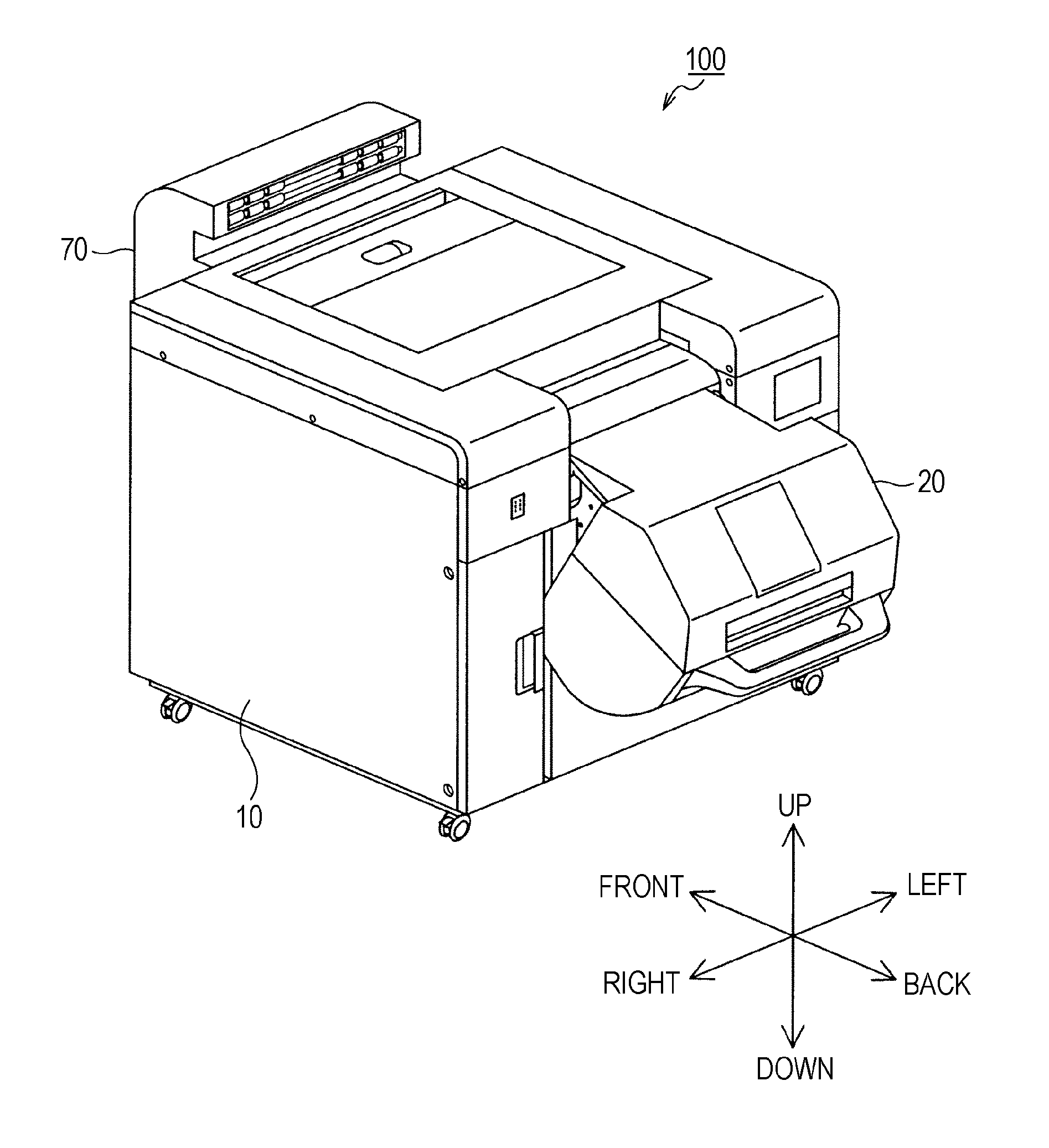
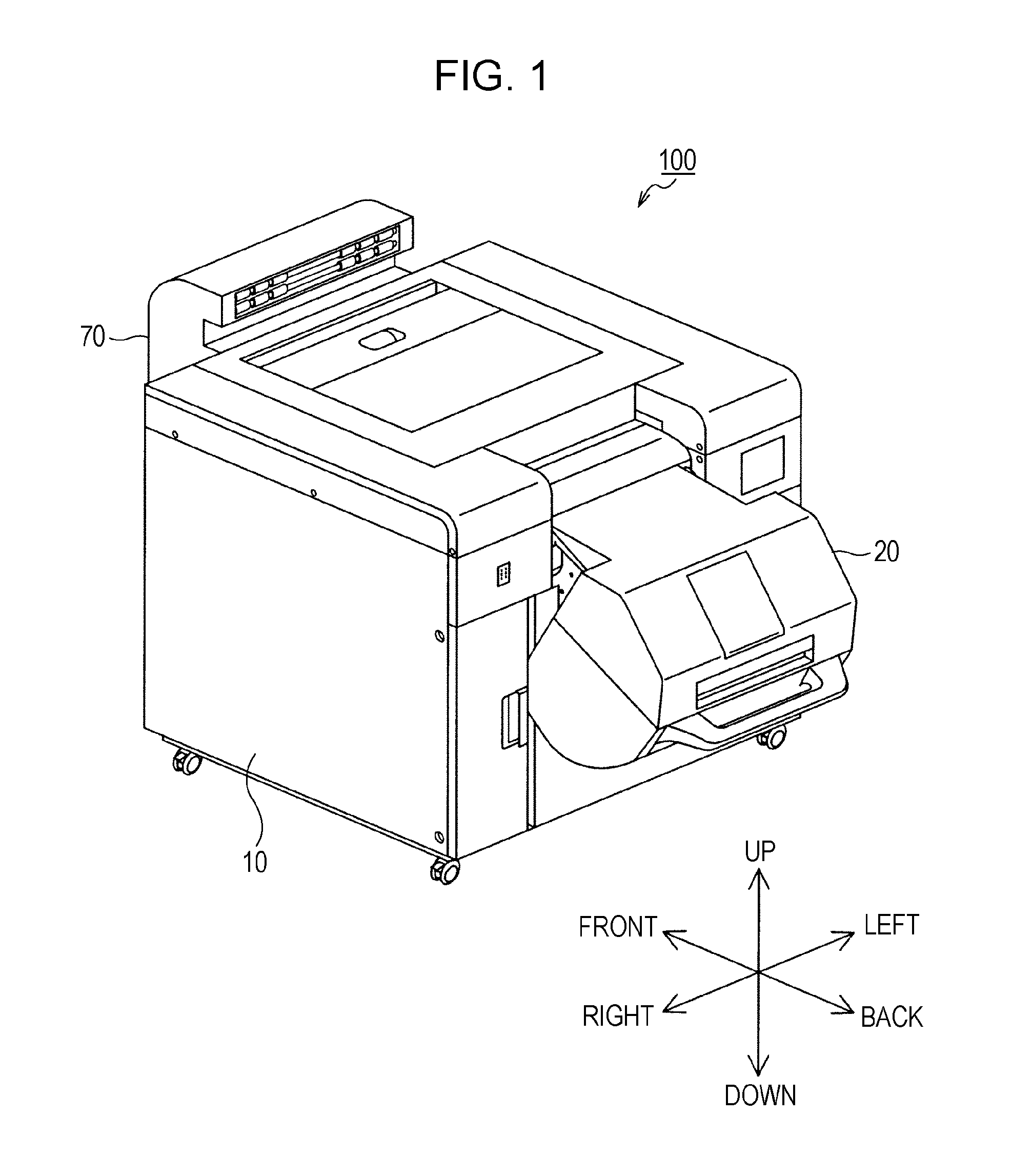
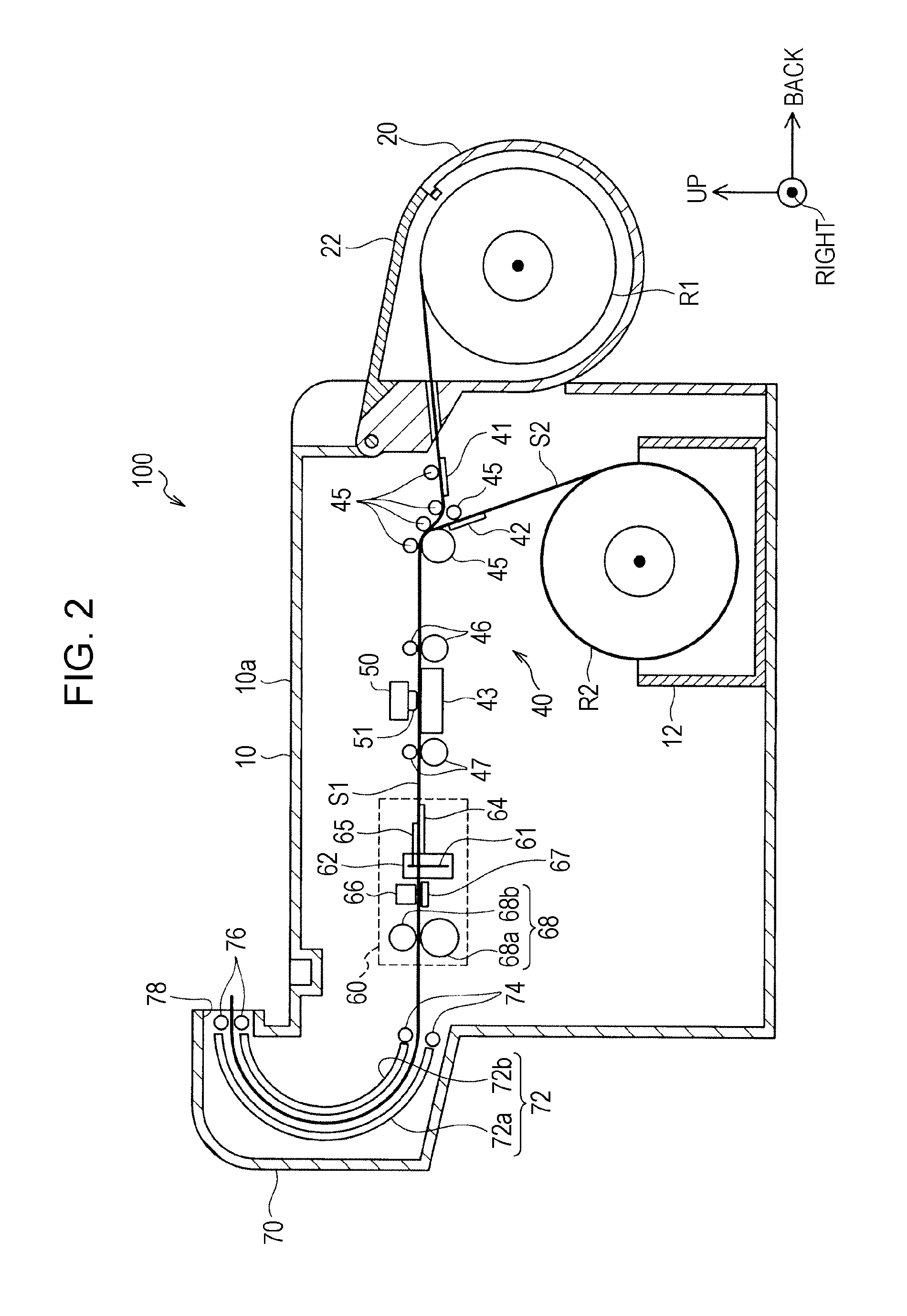
[0034]FIG. 1 is a perspective diagram of an outer appearance of an ink jet printer 100 according to a first embodiment of the invention. FIG. 2 is a schematic configuration diagram illustrating an outline of an internal configuration of the ink jet printer 100. Here, in the description below, in cases of “front and rear direction”, “up and down direction”, and “left and right direction” refer to “front and rear direction”, “up and down direction”, and “left and right direction” shown by the arrows in FIG. 1 (and FIG. 2) in the absence of particular description.

[0035]As shown in FIG. 1, the ink jet printer (referred to below simply as “printer”) 100 is provided with a paper feeding device 20 on a rear side of a printer main body 10 and a paper discharge device 70 on a front side of the printer main body 10, and has a configuration where a sheet S1 (FIG. 2) which is a recording medium with an elongated sha...

second embodiment

B. Second Embodiment

[0076]FIG. 8 is a block diagram illustrating an electrical configuration of a printer 300 according to a second embodiment of the invention with the host computer200. Compared to the printer 100 in the first embodiment, the printer 300 is different in that a cutter error detection section 387 is provided. The hardware differs only in this point and the other hardware is the same as the first embodiment. The same reference numerals as the first embodiment are applied in the configuration which is the same as the first embodiment.

[0077]The cutter device 60 (FIG. 1) is configured by being provided with the cutter carriage 62 which is provided with rotary cutter 61 as described in the first embodiment, but when the cutter carriage 62 moves, an error may occur where the cutter carriage 62 is stopped due to a paper jam. The cutter error detection section 387 detects abnormal stoppages of the cutter carriage 62 by detecting the position of the cutter carriage 62 and is ...

third embodiment

C. Third Embodiment

[0083]A third embodiment of the invention will be described. Compared to the printer 100 in the first embodiment, the printer according to the embodiment is different only in regard to the process of step S190 in the job printing control process (FIG. 6) executed by the CPU 91, and other steps and the configuration of the hardware is the same. Here, the description is performed below with the same reference numerals as the first embodiment being applied to the configuration which is the same as the first embodiment.

[0084]FIG. 10 is a flow chart illustrating a cutting switchover process which is executed according to the third embodiment. The cutting switchover process is executed instead of step S190 in the job printing control process (FIG. 6). That is, in a case where it is determined in step S180 in FIG. 6 that the cutter blade 61 is at the cutting position which is determined from the boundary position between the current image and the immediately previous ima...


PUM


Abstract

A printer includes a transport section which transports a medium, an image recording section which records and lines up a plurality of images in longitudinal direction of the medium based on an image data set which includes a plurality of image data, and a cutting section which obtains image sheets with one image at a time recorded thereon due to cutting of the medium in a width direction of the medium, where the cutting section is provided with a leading edge cutting section which cuts once at a position on a downstream side in the transport direction with regard to a first image out of the plurality of images, and a between-image cutting section which cuts twice at each position between two adjacent images out of the plurality of images where a predetermined margin has been provided.

Description

[0001]Priority is claimed under 35 U.S.C. §119 to Japanese Application No. 2001-206404 filed on Sep. 15, 2010 which is hereby incorporated by reference in its entirety.BACKGROUND[0002]1. Technical Field[0003]The present invention relates to a recording device which records an image on a recording medium with an elongated shape and a recording and cutting control method.[0004]2. Related Art[0005]In recent years, along with widespread use of digital cameras, various recording devices have been proposed which record digital image data with image quality equivalent to that of a silver halide photograph. As one of these recording devices, there is a recording device where an image sheet with one image at a time recorded thereon is obtained by a plurality of images being printed out on an elongated sheet which is rolled up into a roll shape (so-called paper roll) and the sheet being cut using an auto cutter (for example, JP-A-2003-266832).[0006]Here, the plurality of images are printed co...

Claims


Application Information

Patent Timeline
IPC IPC(8): G06K15/02
CPCB41J11/70B41J11/663
Inventor TSUJI, HIROYUKI
Owner SEIKO EPSON CORP
Why Eureka
Try Eureka