Golf Ball
- Summary
- Abstract
- Description
- Claims
- Application Information
AI Technical Summary
Benefits of technology
Problems solved by technology
Method used
Image
Examples
first embodiment
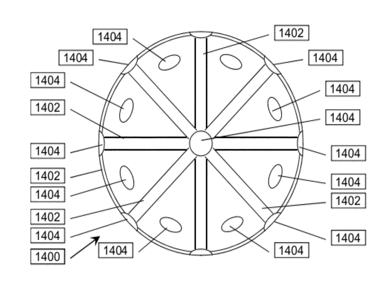
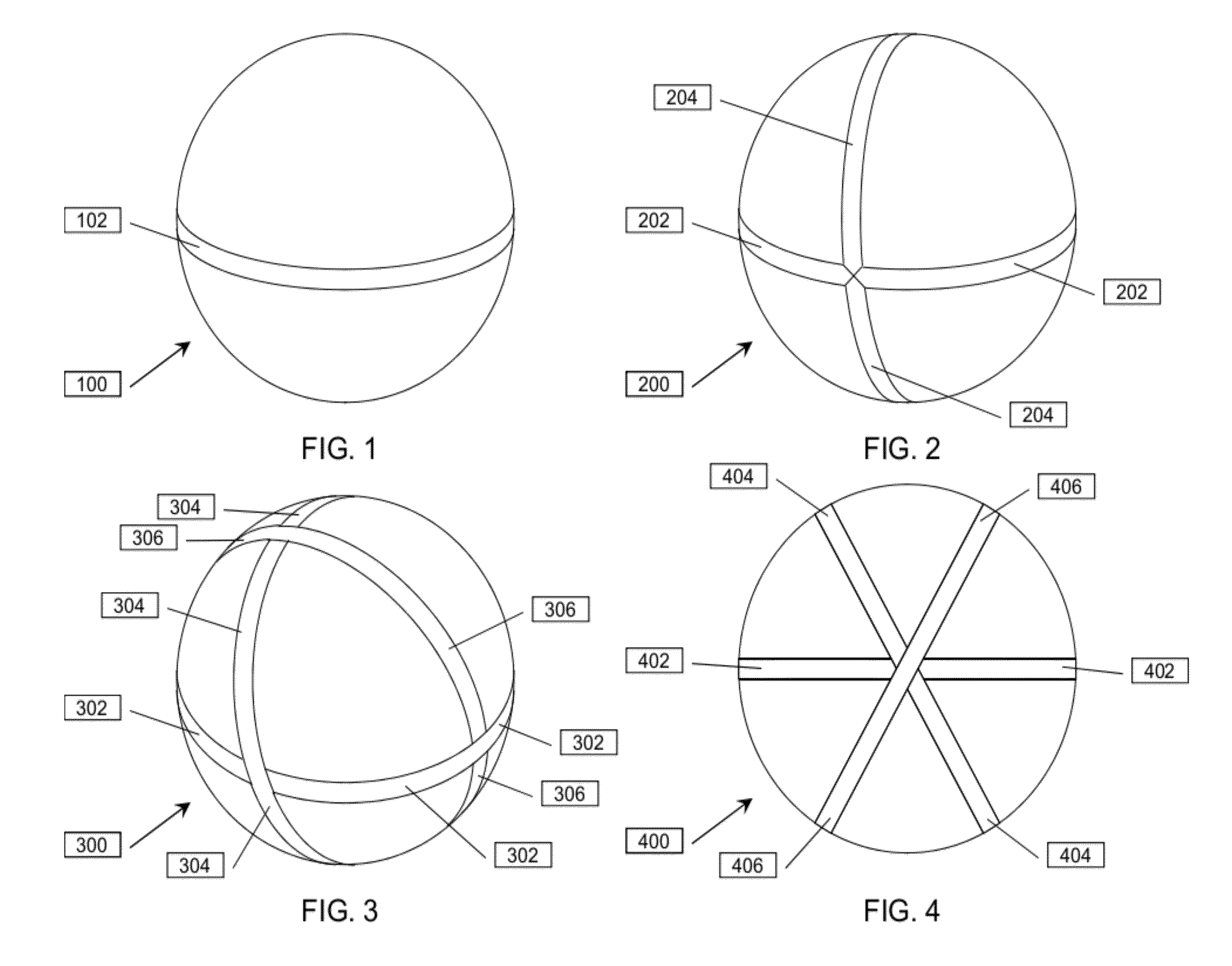
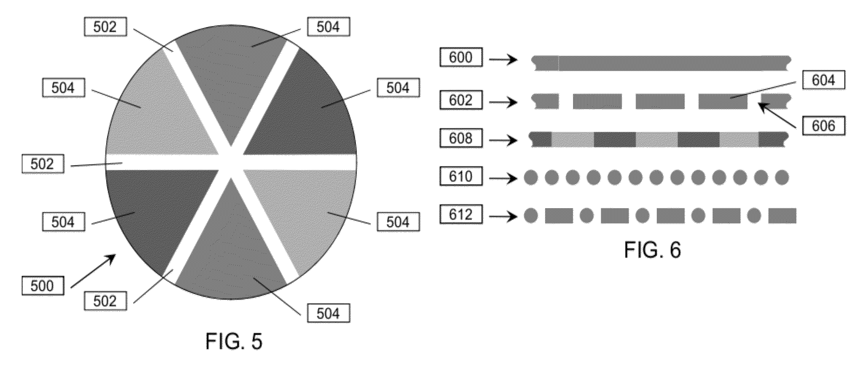
[0023]FIG. 1 depicts a golf ball (100) formed according to a The golf ball (100) has exactly one continuous dynamic focus pattern (102) disposed on an exterior surface of the golf ball (100). A center of a circle traced by the continuous dynamic focus pattern (102) coincides with a center of the golf ball (100). The continuous dynamic focus pattern (102) is between 0.5 and 8 millimeters wide. The continuous dynamic focus pattern (102) may be a solid pattern, or a linear pattern of circles, squares, or other shapes so as to form a stripe. The continuous dynamic focus pattern (102) may be one color, for example, black, red, blue or green, or may be composed of more than one color, such as alternating red and black areas, so as to form a stripe.
second embodiment
[0024]FIG. 2 depicts a golf ball (200) formed according to a The golf ball (200) has exactly two continuous dynamic focus patterns: a first continuous dynamic focus pattern (202) and a second continuous dynamic focus pattern (204) disposed on an exterior surface of the golf ball (200). A center of a first circle traced by the first continuous dynamic focus pattern (202) coincides with a center of the golf ball (200). Similarly, a center of a second circle traced by the second continuous dynamic focus pattern (204) coincides with the center of the golf ball (200). The first continuous dynamic focus pattern (202) is between 0.5 and 8 millimeters wide. Similarly, the second continuous dynamic focus pattern (204) is between 0.5 and 8 millimeters wide. The first continuous dynamic focus pattern (202) may be a solid pattern, or a linear pattern of circles, squares, or other shapes so as to form a stripe. Similarly, the second continuous dynamic focus pattern (204) may be a solid pattern,...
third embodiment
[0026]FIG. 3 depicts a golf ball (300) formed according to a The golf ball (300) has exactly three continuous dynamic focus patterns: a first continuous dynamic focus pattern (302), a second continuous dynamic focus pattern (304) and a third continuous dynamic focus pattern (306) disposed on an exterior surface of the golf ball (300). A center of a first circle traced by the first continuous dynamic focus pattern (302), a center of a second circle traced by the second continuous dynamic focus pattern (304), and a center of a third circle traced by the third continuous dynamic focus pattern (306) each coincide with a center of the golf ball (300). The first continuous dynamic focus pattern (302) is between 0.5 and 8 millimeters wide. Similarly, the second continuous dynamic focus pattern (304) is between 0.5 and 8 millimeters wide, and the third continuous dynamic focus pattern (306) is between 0.5 and 8 millimeters wide. The first continuous dynamic focus pattern (302) may be a sol...
PUM
 Abstract
Description
Claims
Application Information
 - R&D
- Intellectual Property
- Life Sciences
- Materials
- Tech Scout
- Unparalleled Data Quality
- Higher Quality Content
- 60% Fewer Hallucinations
Browse by: Latest US Patents, China's latest patents, Technical Efficacy Thesaurus, Application Domain, Technology Topic, Popular Technical Reports.
© 2025 PatSnap. All rights reserved.Legal|Privacy policy|Modern Slavery Act Transparency Statement|Sitemap|About US| Contact US: help@patsnap.com


