Coast stop vehicle and coast stop method

a technology of coast stop and vehicle, applied in the direction of transportation and packaging, machines/engines, roads, etc., can solve problems such as belt slipping

Inactive Publication Date: 2012-04-12
JATCO LTD
View PDF1 Cites 21 Cited by
  • Summary
  • Abstract
  • Description
  • Claims
  • Application Information

AI Technical Summary

Benefits of technology

[0009]According to the present invention, even if the coast stop condition holds during the travel of the vehicle, the stop of the rotation of the drive power source is prohibited in a situation where the belt tightening force of the pulley is predicted to fall below the engaging force of the f

Problems solved by technology

If this line pressure is reduced, the engaging force of the frictional engagement element could exceed the belt tightening force and a belt slipping problem could occur in the case of a hydraulic circuit in which an accumulator is arranged in an oil passage for the frictional engagement

Method used


Image

  • Coast stop vehicle and coast stop method
  • Coast stop vehicle and coast stop method
  • Coast stop vehicle and coast stop method

Examples


first embodiment

[0020]Hereinafter, embodiments of the present invention are described with reference to the accompanying drawings. In the following description, a “speed ratio” of a certain transmission mechanism is a value obtained by dividing an input rotation speed of this transmission mechanism by an output rotation speed thereof. Further, a “lowest speed ratio” is a maximum speed ratio of the transmission mechanism and a “highest speed ratio” is a minimum speed ratio thereof.

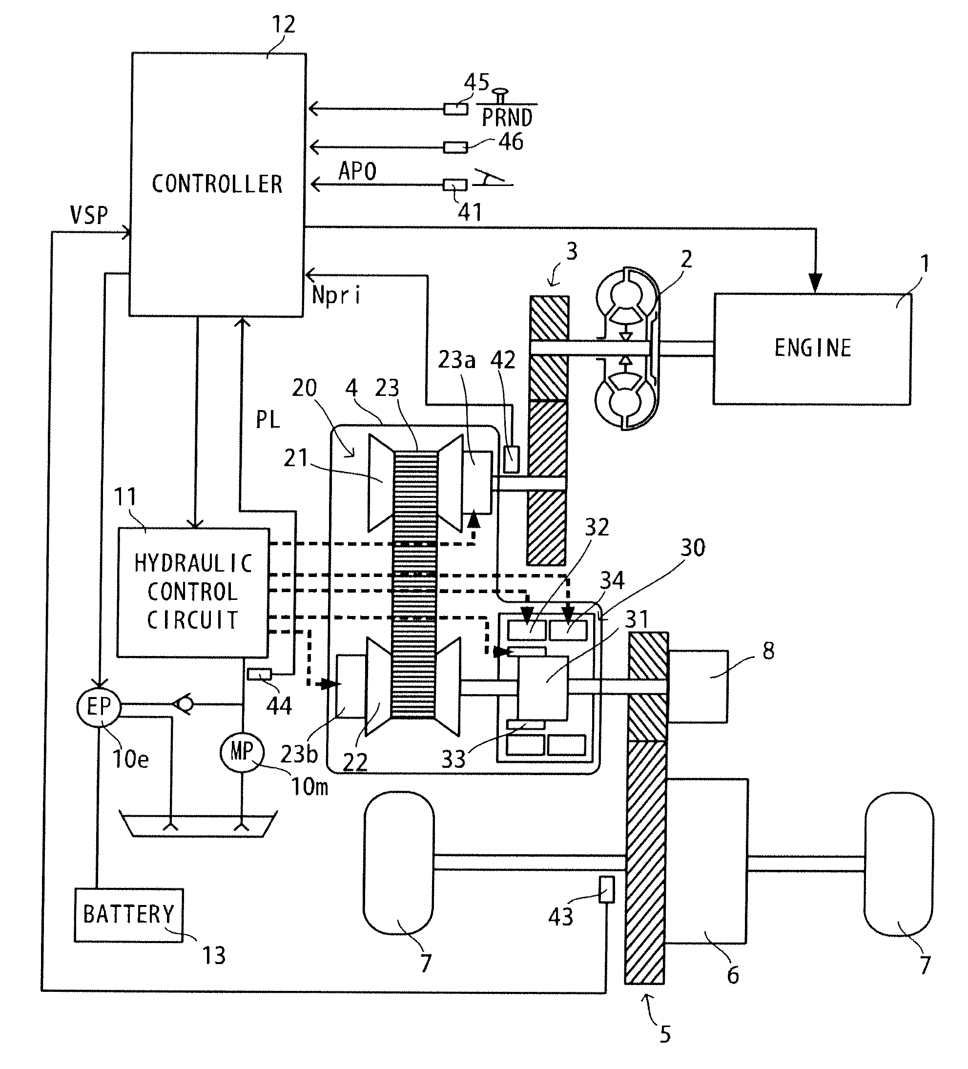
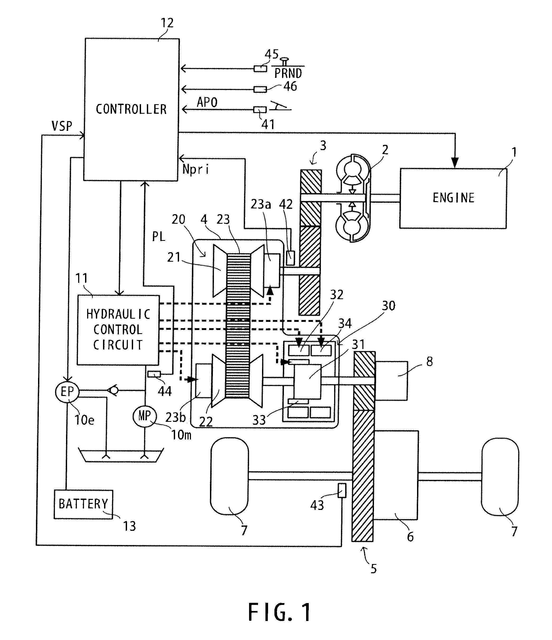
[0021]FIG. 1 is a schematic construction diagram of a coast stop vehicle according to an embodiment of the present invention. This vehicle includes an engine 1 as a drive source, and output rotation of the engine 1 is transmitted to drive wheels 7 via a torque converter 2 with a lock-up clutch, a first gear train 3, a continuously variable transmission (hereinafter, merely referred to as a “transmission 4”), a second gear train 5 and a final speed reducer 6. The second gear train 5 includes a parking mechanism 8 for mechan...

second embodiment

[0103]Next, a second embodiment of the present invention is described. In the second embodiment, a hydraulic control circuit 11 differs in construction from the first embodiment. Note that a basic construction (FIGS. 1 to 3) of the second embodiment is the same as that of the first embodiment and not described.

[0104]FIG. 9 is a diagram showing the construction of the hydraulic control circuit 11 according to the second embodiment of the present invention.

[0105]The hydraulic control circuit 11 includes a mechanical oil pump 10m driven by drive power of an engine 1. A hydraulic pressure produced by the mechanical oil pump 10m is adjusted to a predetermined line pressure by a pressure regulator valve 51 and distributed to respective components of a variator 20 and a sub-transmission mechanism 30 via an oil passage 50.

[0106]In the variator 20, the line pressure is supplied to an oil chamber of a hydraulic cylinder 23b of a secondary pulley 22 as in the above first embodiment. Further, t...


PUM


Abstract

A coast stop vehicle includes a variator which continuously changes a speed ratio by changing a winding diameter of a belt mounted on pulleys, a sub-transmission mechanism connected in series with the variator and shifting discrete gear positions by changing engaged states of a plurality of frictional engagement elements, and a coast stop unit which stops the rotation of the drive power source and releases the engaged frictional engagement element when the coast stop condition holds during travel. The coast stop unit includes a coast stop prohibiting unit which prohibits the coast stop regardless of the coast stop condition when it is predicted at the time of determining whether or not the coast stop condition holds that a belt tightening force of the pulley falls below an engaging force of the frictional engagement element in the engaged state by the execution of the coast stop.

Description

TECHNICAL FIELD OF THE INVENTION[0001]The present invention provides a coast stop vehicle which can stop a drive power source during travel and prevents belt slip.BACKGROUND OF THE INVENTION[0002]An idle stop control is known which stops an engine as a drive power source in a stopped state of a vehicle. Further, a vehicle (see JP2006-170295A) is known which stops an engine also during travel. Engine fuel economy can be improved by such a control.SUMMARY OF THE INVENTION[0003]A continuously variable transmission is developed which enlarges a shift area by combining a variator capable of continuously shifting a speed ratio and a sub-transmission mechanism having stepped gear positions. If a control to stop an engine during travel (hereinafter, referred to as coast stop) is executed in this continuously variable transmission as described above, the following situation may occur.[0004]If the rotation of an oil pump connected to a rotary shaft of the engine is also reduced by the stop of...

Claims


Application Information

Patent Timeline
IPC IPC(8): B60W10/107
CPCB60W10/02B60W10/06B60W10/107B60W10/30B60W30/18072Y10T477/624B60W2540/10B60W2540/16B60W2710/1083Y10T477/6203B60W2520/10B60W10/101Y02T10/60F16H61/02F02D29/00F02D17/00
Inventor AOYAMA, NORITAKAYAMADA, NAOHIROTATEWAKI, KEICHIWATANABE, SHINICHIRO
Owner JATCO LTD
Why Eureka
Try Eureka