
Cold supply system and control method thereof

A control method and technology of a cooling system, applied in refrigerators, refrigeration and liquefaction, lighting and heating equipment, etc., can solve the problems of insufficient cooling, destruction of refrigerant circulation pipelines, and high pressure, so as to reduce pipeline pressure and protect damage effect

Active Publication Date: 2017-12-01
GREE ELECTRIC APPLIANCES INC
View PDF5 Cites 0 Cited by
  • Summary
  • Abstract
  • Description
  • Claims
  • Application Information

AI Technical Summary

Problems solved by technology

[0003] At present, the cooling methods of equipment or electronic components in the industry mainly adopt natural air cooling or forced water cooling. Natural air cooling and forced air cooling can usually meet the heat dissipation requirements in general needs, but for precision instruments with higher temperature requirements , prone to insufficient cooling, therefore, air conditioning systems have been used for cooling precision instruments or equipment, but the current cooling system has only one refrigerant circulation pipeline similar to ordinary household single-cooling air conditioners When the equipment is in non-working state, due to the change of ambient temperature, it is very easy to cause the refrigerant stored in the refrigerant circulation pipeline to evaporate, which will cause the pressure on the low-pressure side of the cooling system to be too high, and even cause damage to the refrigerant circulation pipeline

Method used


Image

  • Cold supply system and control method thereof
  • Cold supply system and control method thereof
  • Cold supply system and control method thereof

Examples


Embodiment Construction

[0028] One of the cores of the present invention is to provide a cooling system so that on the one hand it can meet the cooling demand and on the other hand it can avoid system damage caused by excessive pressure on the low-pressure side of the system.

[0029] Another core of the present invention is to provide a control method for the above-mentioned cooling system.

[0030] In order to enable those skilled in the art to better understand the solution of the present invention, the present invention will be further described in detail below in conjunction with the accompanying drawings and specific embodiments.

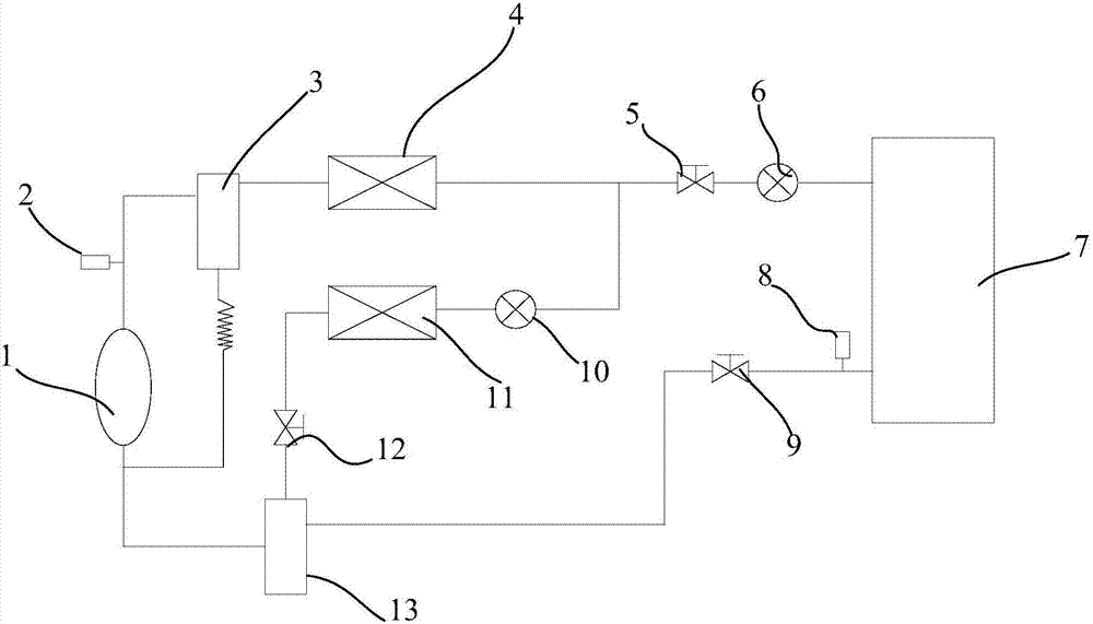
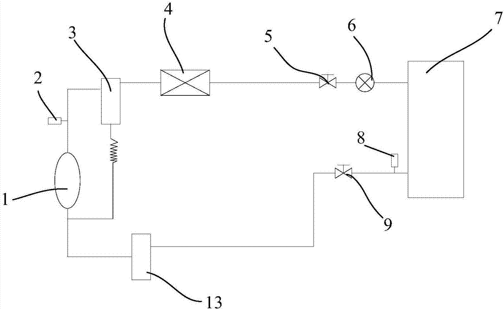
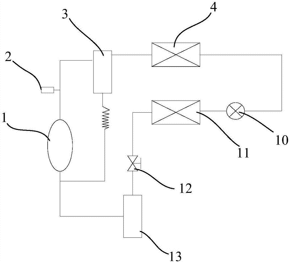
[0031] Please refer to figure 1 , the cooling system disclosed in the present invention includes a common flow path, an auxiliary operation branch and a main operation branch connected in parallel with the auxiliary operation branch. Different, multiple main operation branches can also be set; the common flow path includes the compressor 1 and the condenser 4 connec...


PUM


Abstract

The invention relates to a cold supply system. The cold supply system comprises a sharing runner, an auxiliary running branch and at least one main running branch connected with the auxiliary running branch in parallel, wherein the sharing runner comprises a compressor and a condenser connected with the compressor in series; the auxiliary running branch comprises a first electronic expansion valve, an auxiliary evaporator and a first electromagnetic valve which are sequentially connected in series, the first electronic expansion valve is communicated with the condenser, and the first electromagnetic valve is communicated with an air inlet of the compressor; and the main running branch comprises a second electromagnetic valve, a second electronic expansion valve, a main evaporation pipe, a low pressure sensor and a third electromagnetic valve which are sequentially connected in series, the second electromagnetic valve is communicated with a liquid outlet of the condenser, and the third electromagnetic valve is communicated with an air inlet of the compressor. By means of the cold supply system, effective cooling of a heating device can be achieved, the pipe pressure on the low pressure side of the main running branch is effectively reduced, and the cold supply system is protected against damage. The invention further discloses a control method of the above cold supply system.

Description

technical field [0001] The invention relates to the technical field of production and manufacture of cooling equipment, in particular to a cooling system and a control method thereof. Background technique [0002] In the process of industrial production and manufacturing, whether it is the equipment itself or the various electronic components used to control the operation of the equipment, a large amount of heat will be generated. This heat needs to be dissipated in time to ensure that the equipment or electronic components can operate reliably. Devices or electronic components have a considerable service life. [0003] At present, the cooling methods of equipment or electronic components in the industry mainly adopt natural air cooling or forced water cooling. Natural air cooling and forced air cooling can usually meet the heat dissipation requirements in general needs, but for precision instruments with higher temperature requirements , prone to insufficient cooling, ther...

Claims


Application Information

Patent Timeline
IPC IPC(8): F25B1/00
CPCF25B1/00
Inventor 张仕强陈敏冯涛郭建民何珍滕天凤
Owner GREE ELECTRIC APPLIANCES INC
Learn More