Motor rotor system

a rotor system and motor technology, applied in the direction of magnetic circuit rotating parts, magnetic circuit shape/form/construction, cooling/ventilation arrangement, etc., can solve the problems of affecting the operation of the motor, etc., to achieve excellent batch-to-batch consistency, simple structure, and convenient installation

Active Publication Date: 2012-05-03
ZHONGSHAN BROAD OCEAN
View PDF6 Cites 19 Cited by
  • Summary
  • Abstract
  • Description
  • Claims
  • Application Information

AI Technical Summary

Benefits of technology

[0006]In view of the above-described problems, it is one objective of the invention to provide a motor rotor system, in which positions of a rotor's magnetic field and inductive magnetic field precisely correspond. The motor rotor system has excellent batch-to-batch consistency, simple structure, and convenient installation, and is suitable for large batch production and can be controlled using sine-wave driving control methods with a position sensor.

Problems solved by technology

If the consistency is insufficient, an abnormal phenomenon will occur when a program used in one motor is used in another one.
In a minor case, motor noise and vibration will be aggravated, efficiency will fall, and unique advantages of a sine-wave motor will be lost.
In a serious case, a motor will jitter and lose synchronization.
Present rotor systems also have the following problems: 1. if a first-level magnetic inductive ring is added behind a main magnetic field of a motor, the following problems will occur that relative position between the main magnetic field and the inductive magnetic field is not easy to be controlled and measurement accuracy will be affected due to low accuracy; 2. if an enterprise having a relatively good magnetizing process uses the main magnetic field and the inductive magnetic field together for magnetizing, it is not suitable for strong magnetic materials such as sintered NdFeB but low magnetic materials such as ferrite or bonded NdFeB because of limited process; 3. If an adjustable Hall component is mounted behind the rear cover of a motor, operators can drag the counter EMF to measure relative position of Hall signals and counter EMF waveform and then adjust the Hall component to achieve the required relative position relationship between the main magnetic field and the inductive magnetic field.
However, disadvantages of this method are obvious including poor processability, low overall accuracy, big differences of motor performance, and unfriendly installation.

Method used


Image

  • Motor rotor system
  • Motor rotor system
  • Motor rotor system

Examples


Embodiment Construction

[0030]The invention is explained in further detail below with the aid of the example embodiments and attached drawings.

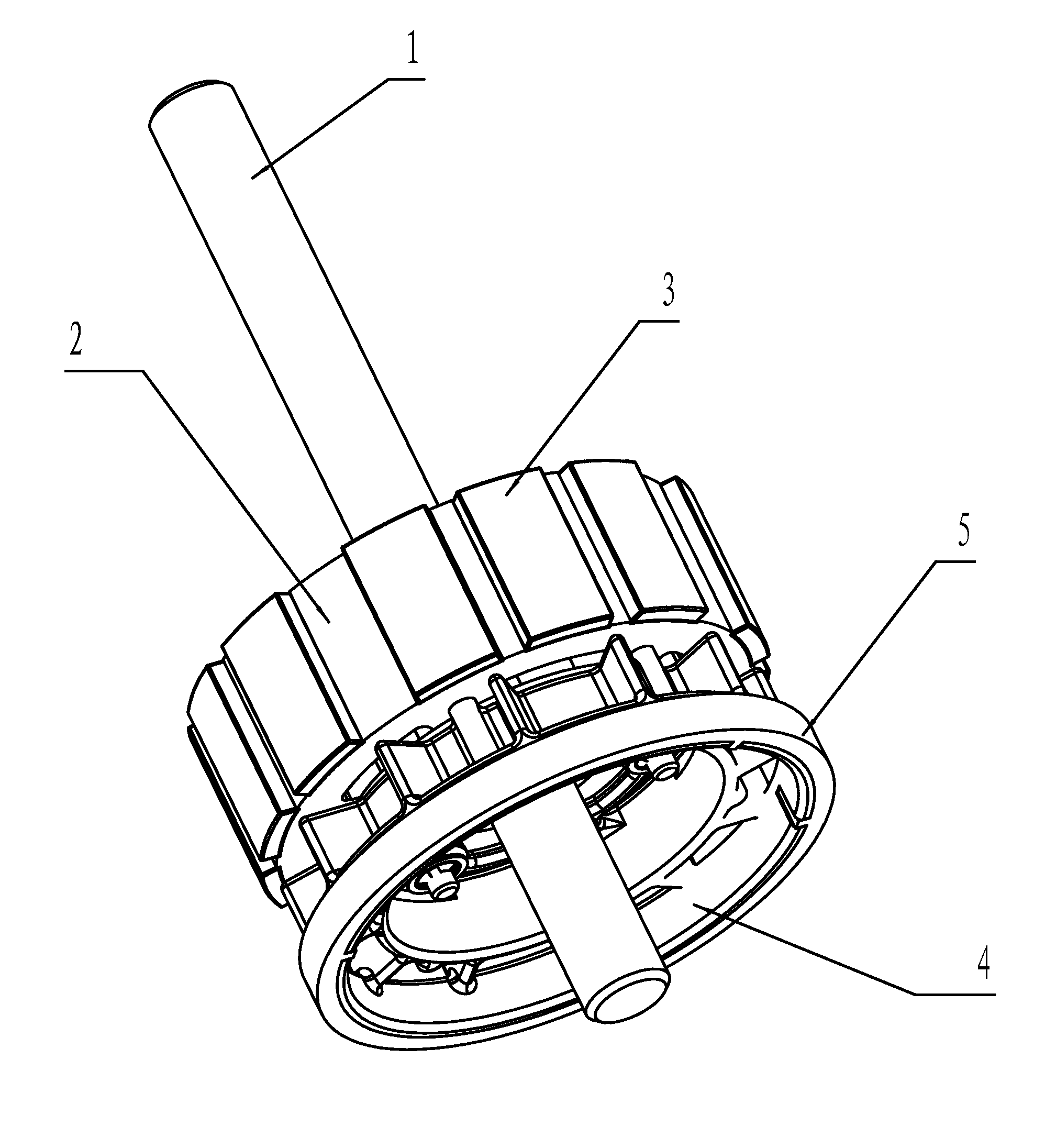
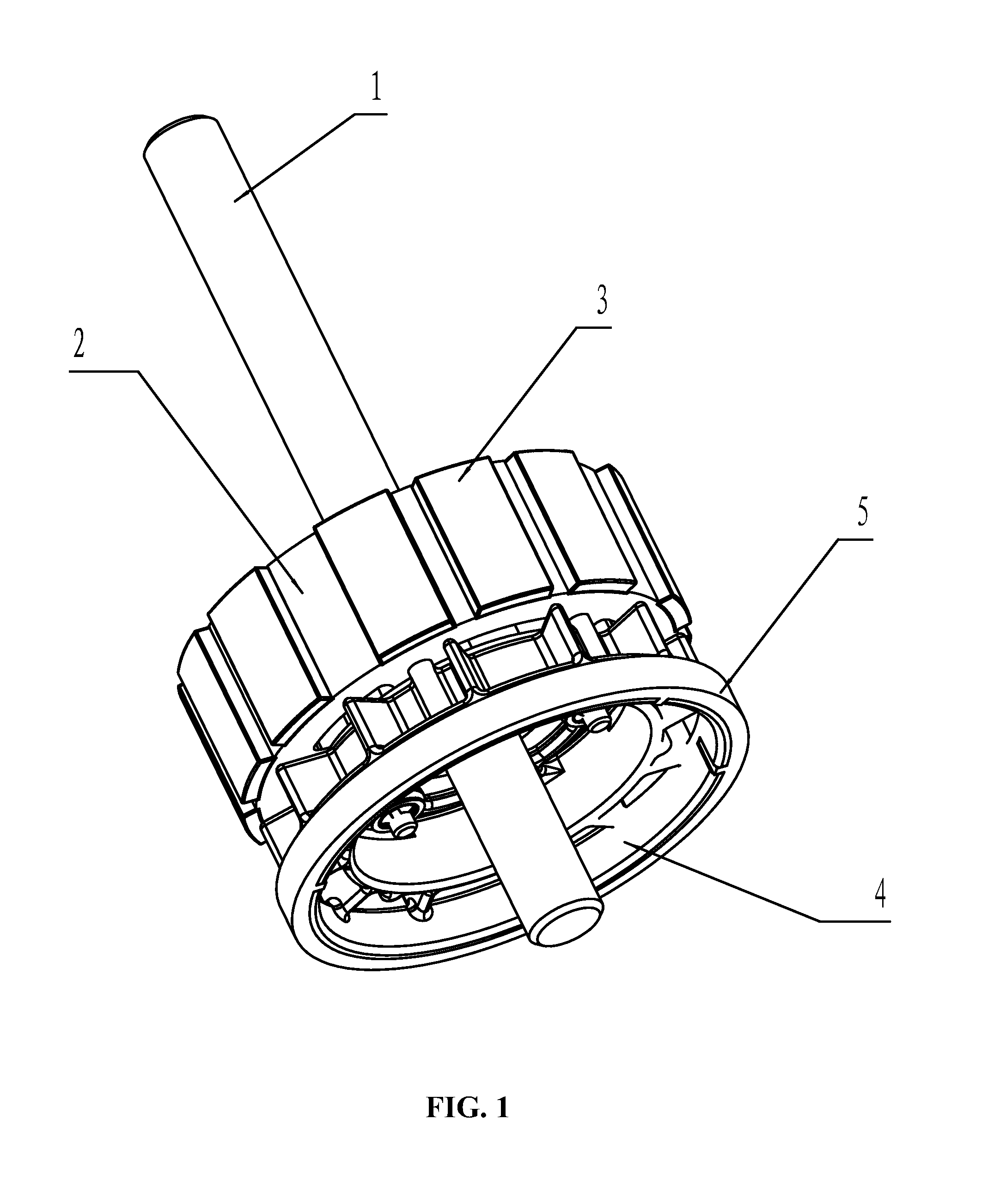
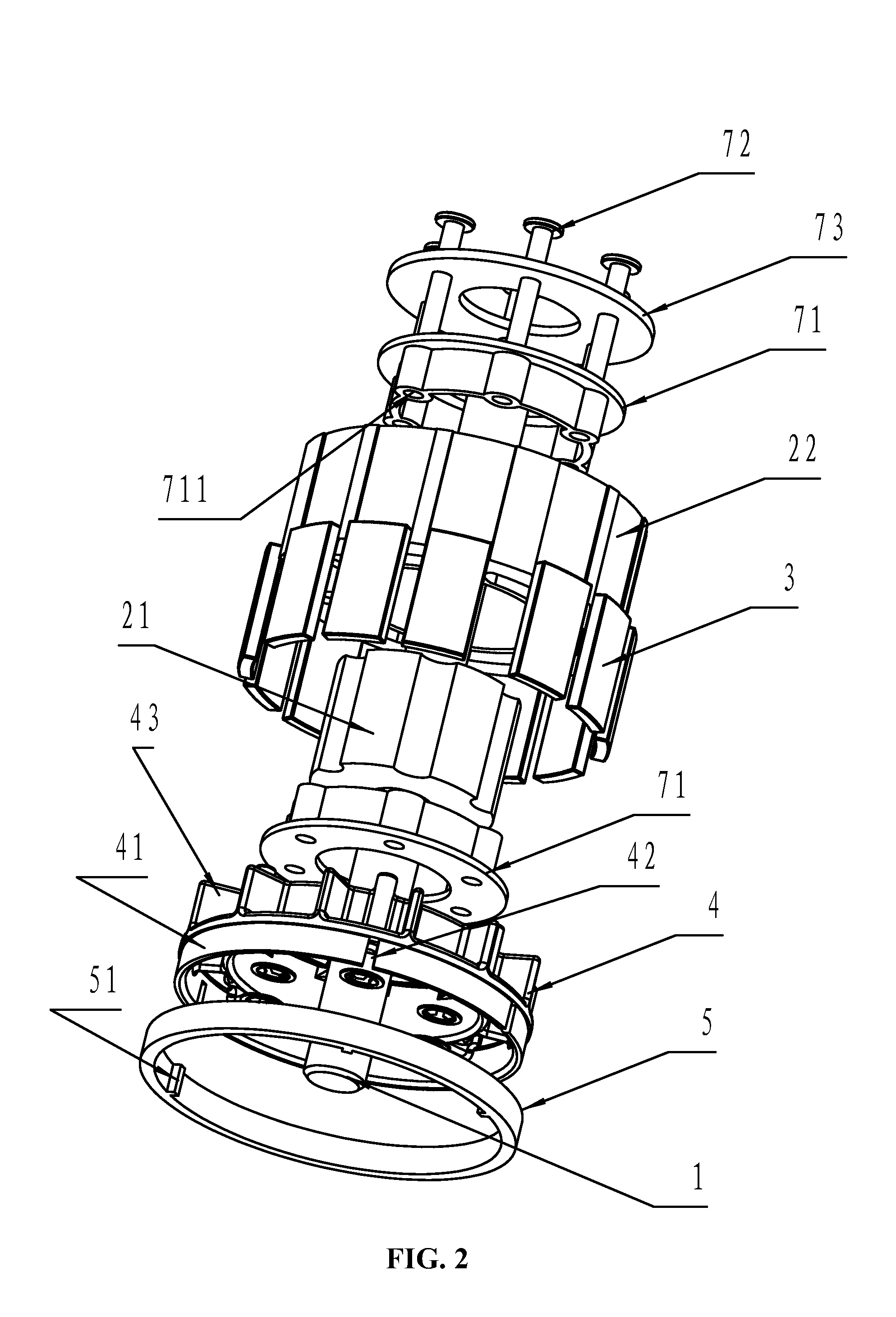
[0031]As shown in FIGS. 1-9, a motor rotor system comprises an axis of rotation 1; a rotor iron core 2 mounted on the axis of rotation 1; a permanent magnet 3, a magnetic ring bracket 4, and a magnetic ring 5, the three are mounted on the rotor iron core 2. The magnetic ring 5 is sheathed on the magnetic ring bracket 4. The magnetic ring bracket 4 is located at one end of the rotor iron core 2 and connected with an end face of the rotor iron core 2. An annular outer side wall 41 of the magnetic ring bracket 4 has a locating slot 42. An inner side wall of the magnetic ring 5 has a positioning convex part 51 and the positioning convex part 51 and the locating slot 42 are embedded together to enable the magnetic ring 5 to be mounted on the outer side of the magnetic ring bracket 4. The magnetic ring bracket 4 is arranged with an annular inner ring 45. A plurality of co...


PUM


Abstract

A motor rotor system including: an axis of rotation, a rotor iron core mounted on the axis of rotation, a permanent magnet, a magnetic ring bracket, and a magnetic ring. The permanent magnet, the magnetic ring bracket, and the magnetic ring are mounted on the rotor iron core. The magnetic ring is sheathed on the magnetic ring bracket. The magnetic ring bracket is located at one end of the rotor iron core and connected with an end face of the rotor iron core. The motor rotor system has excellent batch-to-batch consistency, simple structure, and convenient installation. It is suitable for large batch production and can be controlled using sine-wave driving control methods with a position sensor.

Description

CROSS-REFERENCE TO RELATED APPLICATIONS[0001]This is a continuation-in-part of U.S. patent application Ser. No. 12 / 877,124, filed on Sep. 8, 2010, now pending. Pursuant to 35 U.S.C. §119 and the Paris Convention Treaty, this application also claims the benefit of Chinese Patent Application No. 201010125891.5 filed on Mar. 9, 2010. The contents of all aforementioned applications, including any intervening amendments thereto, are incorporated herein by reference in their entirety.BACKGROUND OF THE INVENTION[0002]1. Field of the Invention[0003]The invention relates to a type of motor rotor system.[0004]2. Description of the Related Art[0005]Conventional brushless DC motors employ a position sensor (Hall element) to measure the position of a rotor so that a motor controller can send a timely phase change command. Now there appears a sine wave control mode with a position sensor. Under such a control mode, a main magnetic field of a motor rotor uses strong magnetism; therefore a driving ...

Claims


Application Information

Patent Timeline
Patent Type & Authority Applications(United States)
IPC IPC(8): H02K21/16H02K5/24H02K9/06
CPCH02K1/278H02K1/28H02K1/30H02K1/32H02K9/06H02K29/08
Inventor PAN, MINGPAN
Owner ZHONGSHAN BROAD OCEAN
Why Eureka
Try Eureka