Fluidic micro-generator of synthetic jets

a technology of synthetic jets and micro-generators, which is applied in the direction of movable spraying apparatuses, spray nozzles, and boundary layer controls, etc., can solve the problems of limiting the speed of the jet, limiting the application, and not being able to adapt the intensity of the jet speed, so as to improve the volume conversion and reduce the dead volume

Active Publication Date: 2012-06-21
OFFICE NAT DETUD & DE RECH AEROSPATIALES
View PDF6 Cites 18 Cited by
  • Summary
  • Abstract
  • Description
  • Claims
  • Application Information

AI Technical Summary

Benefits of technology

[0013]It is understood that the amplification of displacement makes it possible to have a significant amplitude of variation of volume of the cavity. The fact that this is obtained by a mechanical amplitude of displacement mechanism and not by natural resonance of the actuator makes it possible to have this significant amplitude available for frequencies outside the mechanical resonant frequency of the actuator.
[0043]Advantageously, the actuator comprises a first mechanism controlled in frequency or in amplitude, connected in series with a second mechanism controlled in amplitude only. The first mechanism can advantageously comprise a piezoelectric rod and the second mechanism can be a conventional actuator suitable for slow variations. The second mechanism can be used for modifying the position of the point of support of the first mechanism and thus shift the mid point of the travel of the piston and vary the dead volume of the cavity. In particular, it is thus possible to optimise the dead volume of the cavity during the variation of amplitude generated by the first mechanism.

Problems solved by technology

However, the speed of the jets that can be emitted may be limited.
However, such generators of synthetic jets have several drawbacks which limit their applications.
This has the drawback of not being able to adapt the intensity of the speed of the jet as a function of the disturbance of the main flow.

Method used


Image

  • Fluidic micro-generator of synthetic jets
  • Fluidic micro-generator of synthetic jets
  • Fluidic micro-generator of synthetic jets

Examples


Embodiment Construction

:

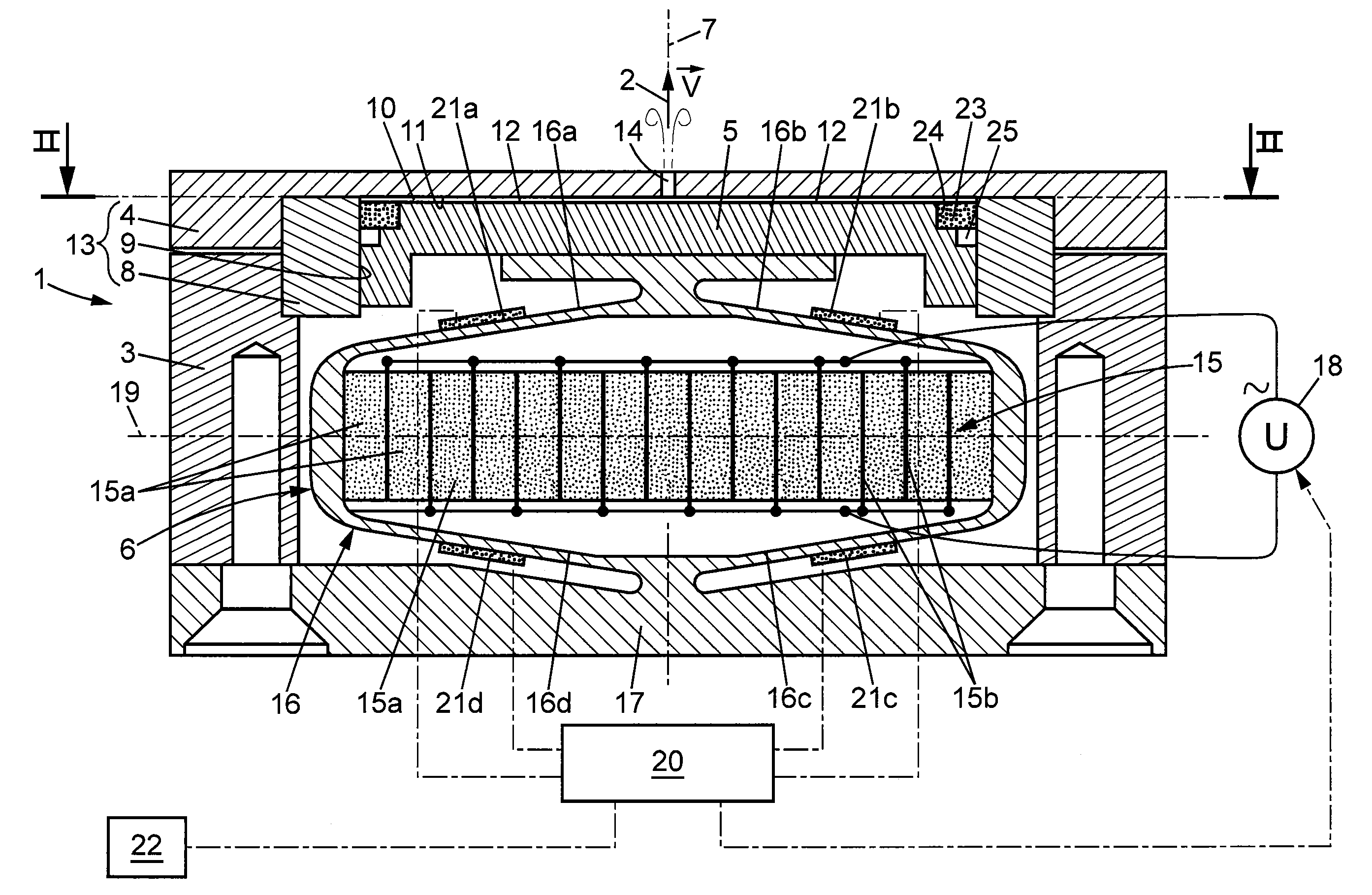
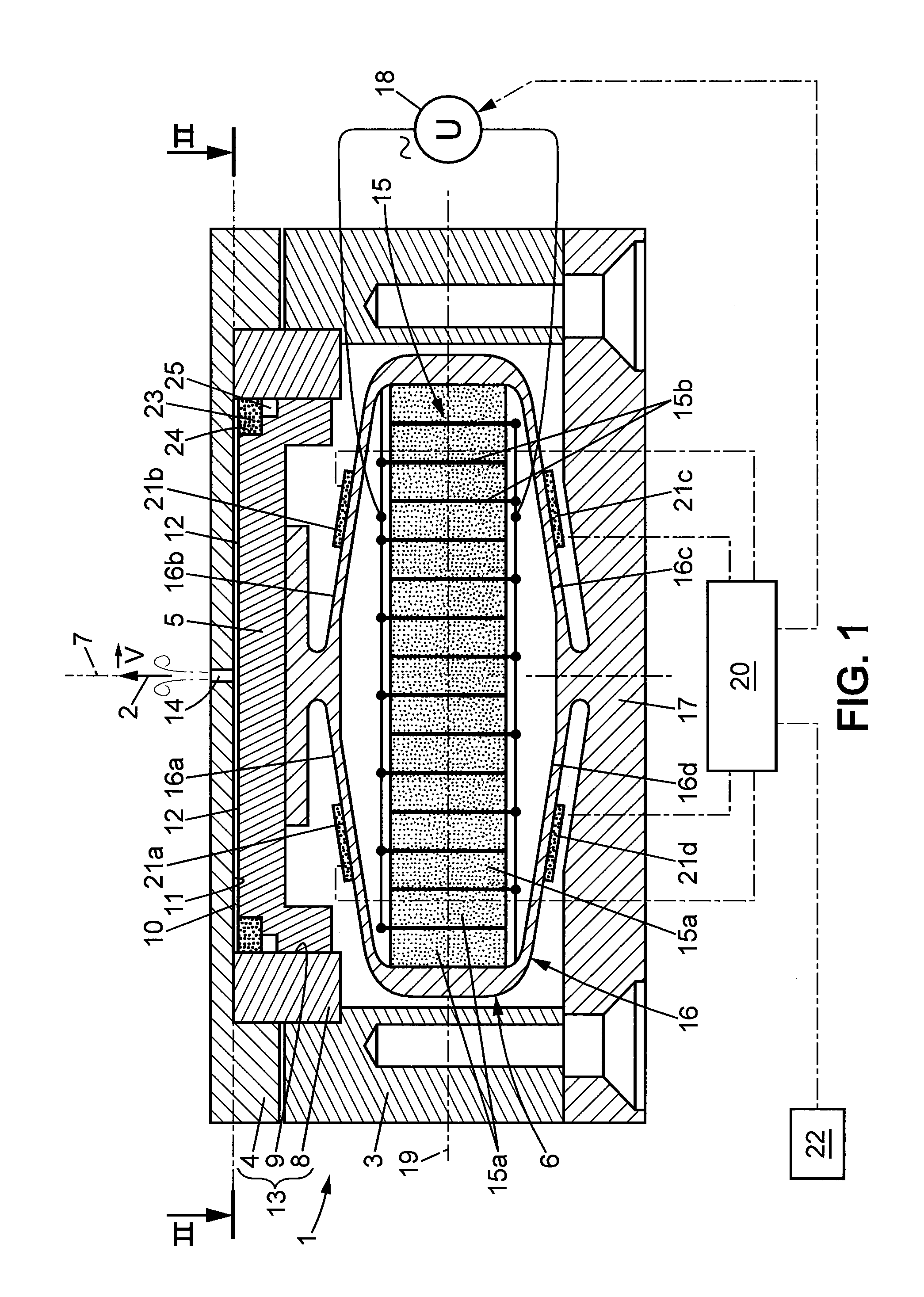
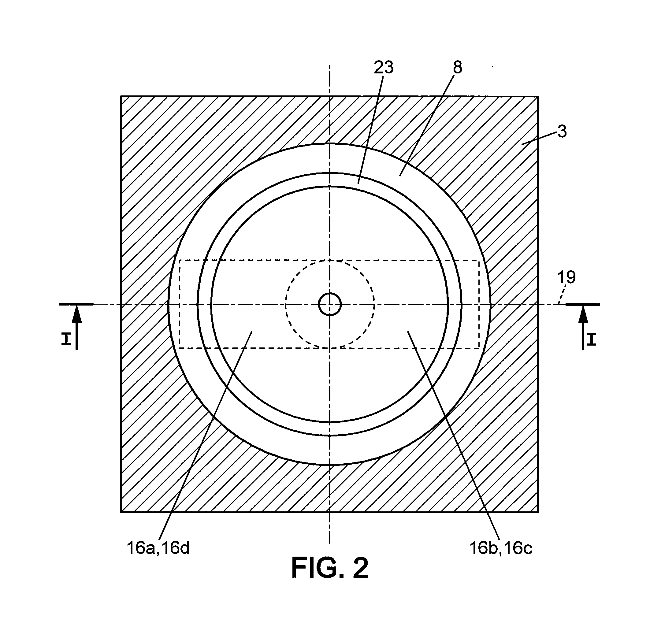
[0054]As shown in FIGS. 1 and 2, the generator 1 of synthetic jets 2 comprises a main body 3 of substantially parallelepipedic external shape, a head 4, a cylindrical piston 5 and an actuator 6. The actuator 6 drives the piston 5 in a direction 7 of sliding of the piston 5. The generator 1 comprises moreover a cylindrical sleeve 8 which is coaxial with the direction 7 of sliding. The cylindrical piston 5 is adjusted to an internal diameter 9 of the sleeve 8. The sleeve 8 also serves as an adjustment shim 8 which is sandwiched between the cover 4 and the main body 3 by a system of screws which is not shown. The generator 1 has a cavity 10 delimited by an internal surface 11 of the head 4 which is flat, and against which the sleeve 8 bears in a fluid-tight manner. The piston 5 has a flat frontal surface 12 parallel to the internal surface 11 of the head 4 and perpendicular to the direction of sliding 7 of the piston 5. The head 4 and the sleeve 8 together constitute a fixed wall 13 d...


PUM


Abstract

Generator (1) of synthetic jets (2) for a main flow of fluid, comprising a cavity (10) delimited by a fixed wall (13) and a mobile wall. The fixed wall comprises a sleeve (8) and a head (4) provided with an orifice (14) through which the generated jet of fluid (2) is drawn in from and ejected into the main flow of fluid. The mobile wall is opposite the head. The generator comprises a rigid piston (3) including the mobile wall and sliding in a fluid-tight manner in the sleeve (8), and comprises an actuator mechanically linked with the piston and able to drive the piston with an alternating movement having an amplitude and a frequency. The actuator is capable of providing a movement of variable amplitude and frequency, at least the amplitude being variable during the movement. The actuator comprises a mechanism for the mechanical amplification of displacement.

Description

PRIORITY CLAIM[0001]The present application claims priority to French application no. 10 60487, filed Dec. 14, 2011, the disclosure of which is hereby incorporated by referenced herein in its entirety.SUBJECT OF THE INVENTION[0002]The invention relates to the field of micro-generators intended for the control of a main flow of fluid by secondary fluidic jets. The main flow of fluid to be controlled can for example be an external aerodynamic flow such as for the hyperlift of aircraft, the control of the buffeting of aircraft wings, the drag of motor vehicles or of trains of railway vehicles. The main flow to be controlled can also be an internal aerodynamic flow such as the air intakes of aircraft engines.[0003]The flow of a fluid around a structure is modified by secondary fluid jets coming from holes passing through the outer surface of the structure. The invention relates in particular to generators of such secondary jets.[0004]Two types of generators of jets situated inside a str...

Claims


Application Information

Patent Timeline
Patent Type & Authority Applications(United States)
IPC IPC(8): B05B1/08
CPCB64C21/04Y02T50/166F15D1/0095B64C2230/18Y02T50/10
Inventor TERNOY, FREDERICUZEEL, ETIENNELANDAES, DIDIER
Owner OFFICE NAT DETUD & DE RECH AEROSPATIALES
Why Eureka
Try Eureka