Donor Locking Rail

Inactive Publication Date: 2012-07-05
J R CLANCY
View PDF4 Cites 0 Cited by
  • Summary
  • Abstract
  • Description
  • Claims
  • Application Information

AI Technical Summary

Benefits of technology

[0008]The present invention is directed to a system and / or method for recognizing a theatre donation by placing a notice on a locking rail sub-system in a theatre. This system and / or method is believed to be rather counterintuitive because the locking rail is generally a low visibility part of the theatre, where the general public does not traditionally go. Despite this low visibility, the present invention is believed to foster a surprisingly large amount of goodwill, the relatively low visibility of the locking rail assembly notwithstanding. Also, because the locking rail is such a critical piece of equipment for safety purposes, the present invention recognizes that the good associations with donors and / or donations will tend to be subtly and psychologically enhanced by the fact that the donation related information is placed on the locking rail assembly.

Problems solved by technology

This system and / or method is believed to be rather counterintuitive because the locking rail is generally a low visibility part of the theatre, where the general public does not traditionally go.

Method used


Image

  • Donor Locking Rail
  • Donor Locking Rail
  • Donor Locking Rail

Examples


Embodiment Construction

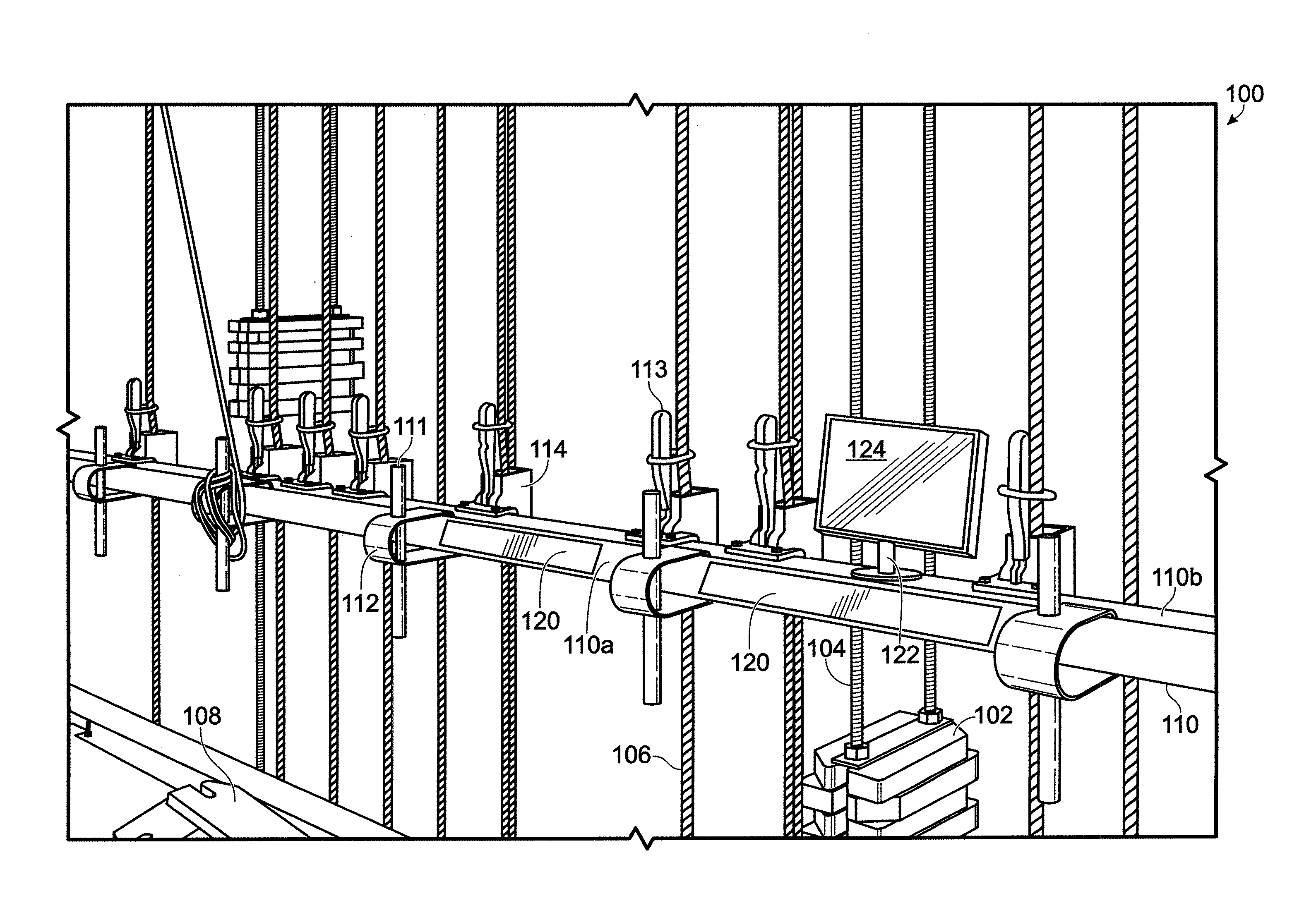
[0016]FIGS. 1 show locking rail assembly 100, including: stacked counterweights 102; counterweight stack guide hardware sub-assembly 104; ropes 106; loose counterweights 108; rail member 110 (including outwards facing surface 110a and upwards facing surface 110b); stationary handles 111; stationary handle brackets 112; movable handles 113; line locking sub-assemblies 114; outwards facing donation-related cards 120; video display bracket 122; and video display screen 124.

[0017]Outwards facing donor cards 120 are any sort of relatively permanent cards that can be printed with donation-related information (see DEFINITIONS section), such as metal plaques or plastic nameplate type displays. Because the cards are relatively permanent, they cannot take forms that are unlikely to remain intact over time. For example, cards 120 are not merely pieces of paper taped onto the rail with cellophane tape. Preferably, mounting of the cards 120 should be relatively permanent, such as by glue or scre...


PUM


Abstract

A system and / or method for recognizing a theatre donation by placing a notice on a locking rail sub-system in a theatre. This system and / or method is believed to be rather counterintuitive because the locking rail is generally a low visibility part of the theatre, where the general public does not traditionally go. Despite this low visibility, the present invention is believed to foster a surprisingly large amount of goodwill, the relatively low visibility of the locking rail assembly notwithstanding. Also, because the locking rail is such a critical piece of equipment for safety purposes, the present invention recognizes that the good associations with donors and / or donations will tend to be subtly and psychologically enhanced by the fact that the donation related information is placed on the locking rail assembly. Also disclosed is a video display (for example, an LCD video display) that is mechanically connected to the rail of a locking rail assembly, and is used to convey information relating to the locking rail assembly.

Description

BACKGROUND OF THE INVENTION[0001]1. Field of the Invention[0002]The present invention relates to theatre equipment and more particularly to locking rails (see DEFINITIONS section) for use with theatre rigging sub-systems (see DEFINITIONS section).[0003]2. Description of the Related Art[0004]A conventional theatre has many sub-systems, such as a building structure sub-system, a seating sub-system, a ventilation, heating and cooling sub-system, a stage and orchestra pit sub-system, and a rigging sub-system. The rigging sub-system includes flexible lines (such as cables or ropes) for moving theatre-related objects (like scenery battens and moveable lighting fixtures). One example of a rigging sub-system, or a part of a rigging sub-system is know as a counterweight arbor fly system. It is conventional for a theatre rigging system to include a locking rail assembly (see DEFINITIONS section).[0005]It is conventional for the seating-sub-system of theatres to include plaques indicating dono...

Claims


Application Information

Patent Timeline
IPC IPC(8): G06Q40/00G09F1/02H04N5/64F16M13/00
CPCG06Q20/10G09F7/18G06Q50/00G09F2007/1856G09F2007/1891G09F2007/1804
InventorTHEIS, JR., ROBERT J.MURPHY, MICHAEL S.
OwnerJ R CLANCY