Comparator and semiconductor device including comparator

a semiconductor device and comparator technology, applied in the field of comparators, can solve the problems of low flexibility of driving method, limited timing of performing normal operation, and inability of chopper comparator to operate as a comparator, and achieve the effects of low cost, high on-state current, and reduced frequency of initialization

Inactive Publication Date: 2012-11-01
SEMICON ENERGY LAB CO LTD
View PDF8 Cites 13 Cited by
  • Summary
  • Abstract
  • Description
  • Claims
  • Application Information

AI Technical Summary

Benefits of technology

[0023]Since the transistor whose off-state current is extremely low is used as the first switch, current (leakage current) flowing through the first switch which is selected to be turned off can be reduced. Thus, after initialization, a change in voltage held in the capacitor is inhibited, so that the malfunction of the comparator can be reduced. Further, the frequency of initialization can be reduced, so that the flexibility of a driving method is high.
[0024]In the case where current flowing through the first switch which is selected to be turned on is increased, that is, the transistor used as the first switch has high on-state current, initialization can be performed at high speed. Here, the on-state current of the transistor can be increased by an increase in channel width of the transistor. However, larger channel width causes a pronounced heat generation problem in the transistor. Thus, a plurality of transistors electrically connected in parallel to each other are used as the first switch. In this manner, heat generation in the plurality of transistors used as the first switch can be inhibited and current flowing through the first switch which is selected to be turned on can be increased. Accordingly, initialization can be performed at higher speed without sacrificing the reliability of the comparator. Further, when the plurality of transistors overlap with each other, current flowing through the first switch which is selected to be turned on can be increased and an increase in area of the first switch can be inhibited. Accordingly, an increase in circuit area can be inhibited and initialization can be performed at higher speed, without sacrificing the reliability of the comparator.
[0025]Note that when a plurality of transistors electrically connected in series with each o

Problems solved by technology

In other words, if the reference voltage Vc is greatly changed by leakage current flowing through the switch 2624 after initialization, the chopper comparator fails, which causes a malfunction.
In other words, the chopper comparator fails, which causes a malfunction.
Note that during initialization, the chop

Method used


Image

  • Comparator and semiconductor device including comparator
  • Comparator and semiconductor device including comparator
  • Comparator and semiconductor device including comparator

Examples


embodiment 1

[0050]One embodiment of a chopper comparator in the present invention is described.

(Structure of Comparator)

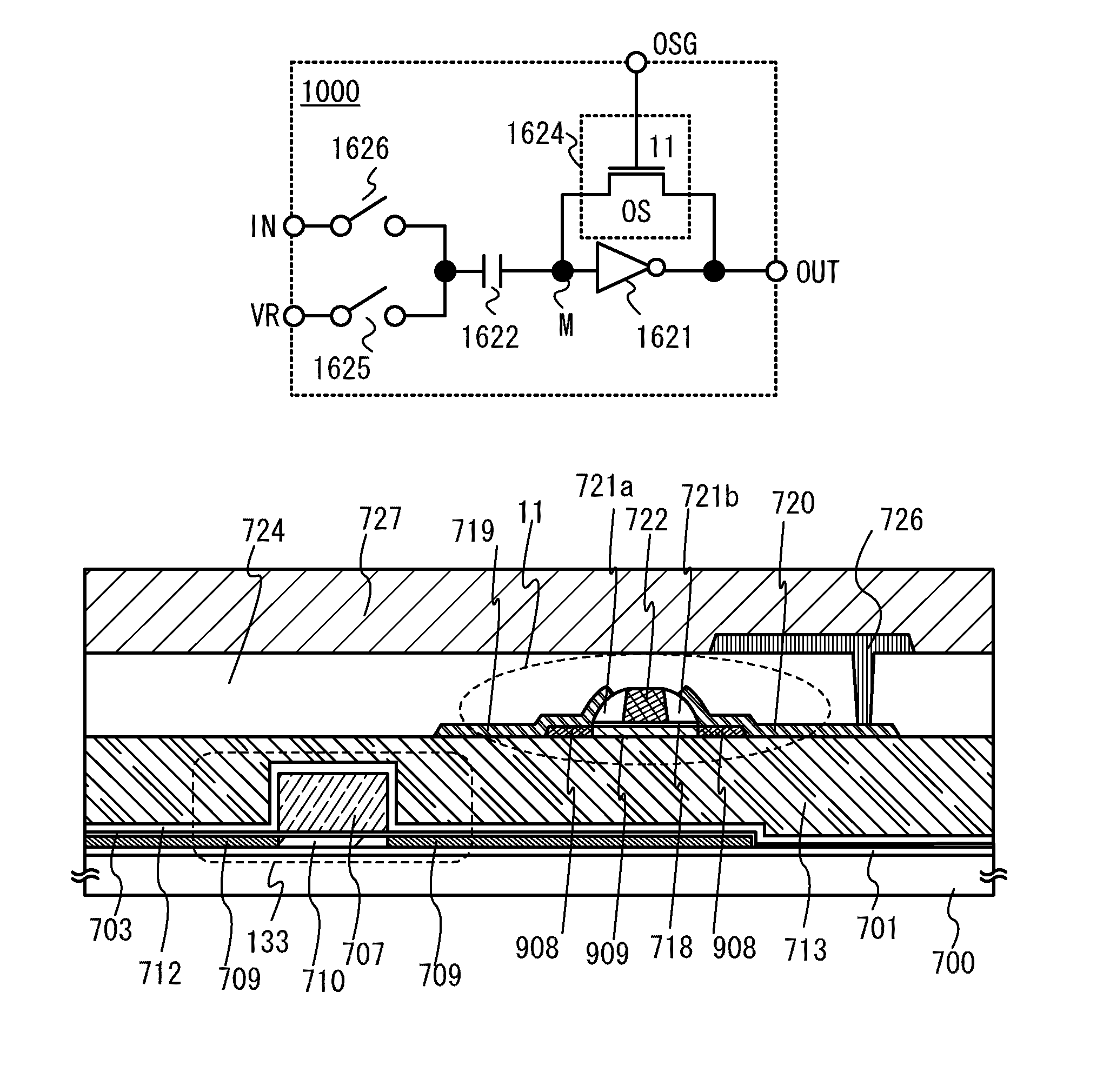
[0051]FIG. 1A is one embodiment of a circuit diagram of a chopper comparator in the present invention. In FIG. 1A, a chopper comparator 1000 includes a switch 1624, a switch 1625, a switch 1626, an inverter 1621, and a capacitor 1622. The switch 1624 is electrically connected in parallel to the inverter 1621. An output terminal of the inverter 1621 is electrically connected to an output terminal (indicated by “OUT” in FIG. 1A) of the chopper comparator 1000. An input terminal of the inverter 1621 is electrically connected to one of a pair of electrodes of the capacitor 1622. Here, the input terminal of the inverter 1621 or the one of the pair of electrodes of the capacitor 1622 is referred to as a node M (indicated by “M” in FIG. 1A). The other of the pair of electrodes of the capacitor 1622 is electrically connected to an input terminal (indicated by “IN” in FIG. 1A) of the c...

embodiment 2

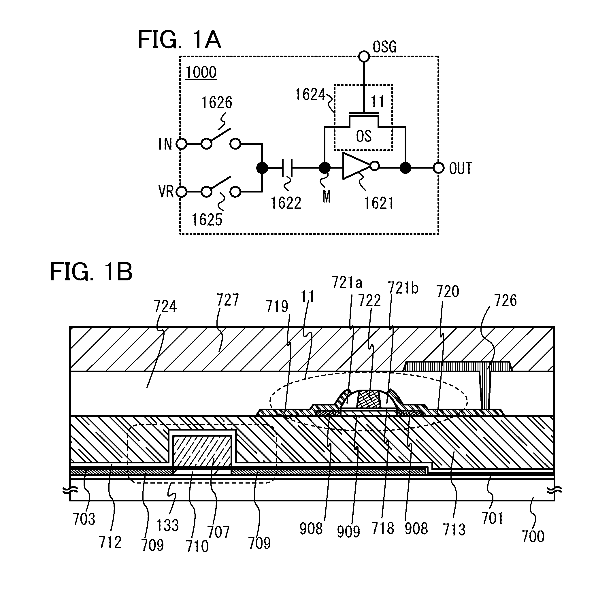
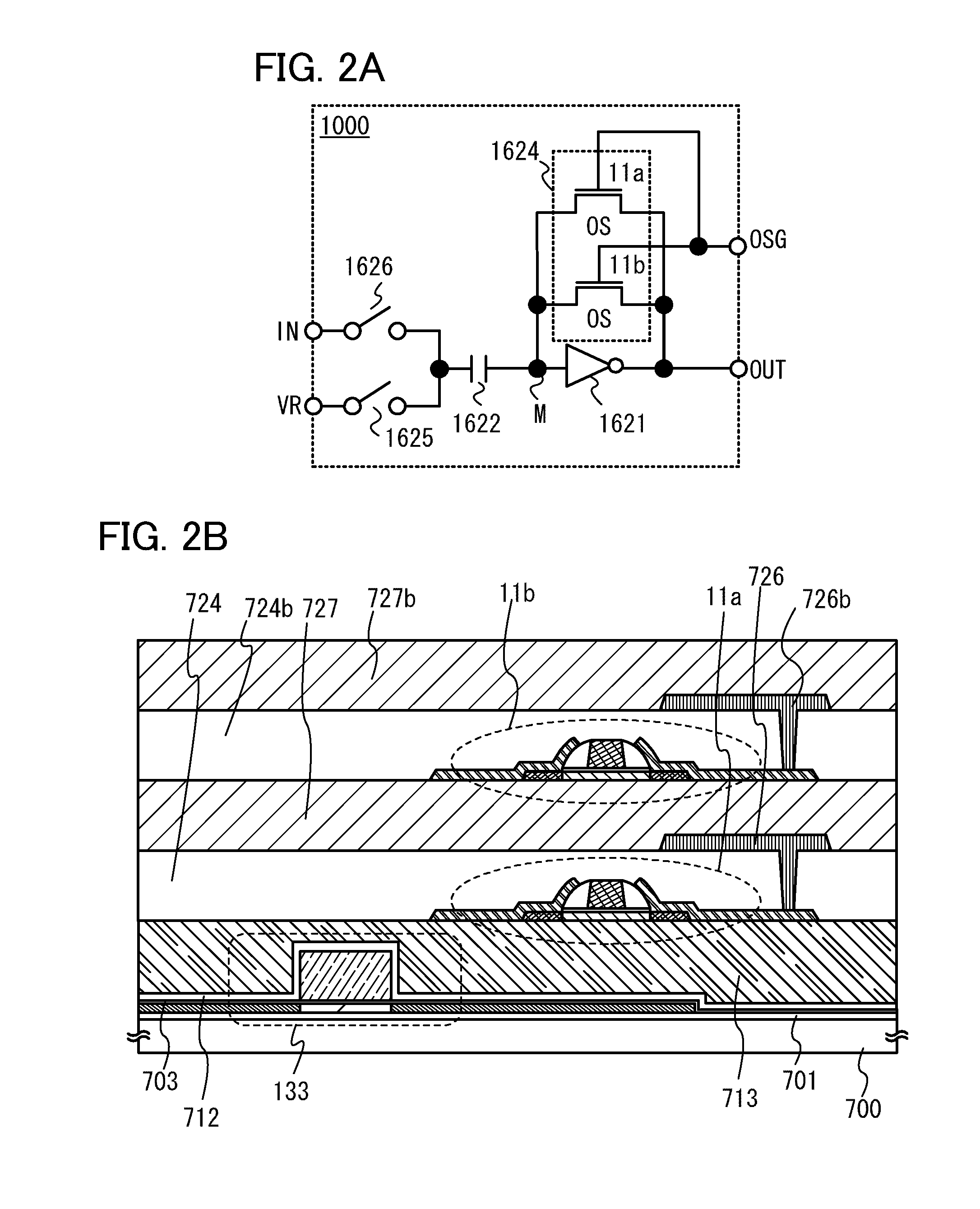
[0062]Another embodiment of a chopper comparator in the present invention is described. FIG. 2A is one embodiment of a circuit diagram of a chopper comparator in the present invention.

[0063]The chopper comparator 1000 in FIG. 2A differs from the chopper comparator 1000 in FIG. 1A in that transistors 11a and 11b electrically connected in parallel to each other are used as the switch 1624, and other structures are similar to those in FIG. 1A; thus, a description thereof is omitted. Note that the switch 1624 is not limited to being constituted of two transistors. A plurality of transistors electrically connected in parallel to each other can be used as the switch 1624. Thus, the value of current flowing through the switch 1624 can be increased, so that initialization can be efficiently performed. Further, heat generation in the transistors can be inhibited.

[0064]A method for driving the comparator 1000 in FIG. 2A is similar to the method for driving the comparator 1000 in FIG. 1A; thus...

embodiment 3

[0068]Another embodiment of a chopper comparator in the present invention is described. FIG. 3A is one embodiment of a circuit diagram of a chopper comparator in the present invention.

[0069]The chopper comparator 1000 in FIG. 3A differs from the chopper comparator 1000 in FIG. 1A in that the transistor 11a and a transistor 11c electrically connected in series with each other, the transistor 11b and a transistor 11d electrically connected in series with each other, and a circuit constituted of the transistors 11a and 11c and a circuit constituted of the transistors 11b and 11d which are electrically connected in parallel to each other are used as the switch 1624. Other structures are similar to those in FIG. 1A; thus, a description thereof is omitted. Note that the switch 1624 is not limited to being constituted of four transistors. A plurality of transistors electrically connected in series and in parallel to each other can be used as the switch 1624. This structure can also be refe...


PUM


Abstract

A chopper comparator with a novel structure is provided. The comparator includes an inverter, a capacitor, a first switch, a second switch, and a third switch. An input terminal and an output terminal of the inverter are electrically connected to each other through the first switch. The input terminal of the inverter is electrically connected to one of a pair of electrodes of the capacitor. A reference potential is applied to the other of the pair of electrodes of the capacitor through the second switch. A signal potential input is applied to the other of the pair of electrodes of the capacitor through the third switch. A potential output from the output terminal of the inverter is an output signal. A transistor whose channel is formed in an oxide semiconductor layer is used as the first switch.

Description

BACKGROUND OF THE INVENTION[0001]1. Field of the Invention[0002]The present invention relates to comparators. In particular, the present invention relates to chopper comparators. Further, the present invention relates to semiconductor devices including chopper comparators. Furthermore, the present invention relates to electronic devices including the semiconductor devices.[0003]2. Description of the Related Art[0004]A differential amplifier (also referred to as an operational amplifier) and a chopper comparator (also referred to as a chopper inverter comparator, an inverter chopper comparator, or the like) are widely used as comparators (comparison circuits). In Patent Document 1 (see FIG. 1 of Patent Document 1), a chopper comparator as illustrated in FIG. 9 is used.[0005]In FIG. 9, a chopper comparator includes an inverter 2621, a capacitor 2622, and switches 2624, 2625, and 2626. The switch 2624 is electrically connected in parallel to the inverter 2621. An output terminal of the...

Claims


Application Information

Patent Timeline
IPC IPC(8): H03K5/153
CPCH03K5/249H03K5/2472
Inventor MIYAKE, HIROYUKI
Owner SEMICON ENERGY LAB CO LTD
Why Eureka
Try Eureka