Electric machine having a plurality of torque-support elements

Inactive Publication Date: 2012-11-22
SIEMENS AG
View PDF11 Cites 0 Cited by
  • Summary
  • Abstract
  • Description
  • Claims
  • Application Information

AI Technical Summary

Benefits of technology

[0014]According to another advantageous feature of the present invention, the stator support elements and holding support elements can possess a greater rigidity in the circumferential direction clockwise or anticlockwise than in any other direction. A very high degree of rigidity can hence be ensured in the circumferential direction whereas a lesser degree of rigidity can be achieved in all other directions in particular in terms of translational movements of the stator relative to the retaining device.
[0015]According to another advantageous feature of the present invention, the stator support elements and the holding support elements can respectively be arranged symmetrically to one another in relation to the axis. A greater degree of torsional rigidity can be achieved thereby than with single-arm torque supports.
[0016]According to ano

Problems solved by technology

If, for example, a torque motor is to drive a separately mounted work machine without a coupling connection on the shaft side, then over-determined bearing will occur.
A force whose counter-forces will have a damaging impact on the motor bearings will hence be transmitted at the securing point between the torque support and machin

Method used


Image

  • Electric machine having a plurality of torque-support elements
  • Electric machine having a plurality of torque-support elements
  • Electric machine having a plurality of torque-support elements

Examples


Embodiment Construction

[0026]Throughout all the figures, same or corresponding elements may generally be indicated by same reference numerals. These depicted embodiments are to be understood as illustrative of the invention and not as limiting in any way. It should also be understood that the figures are not necessarily to scale and that the embodiments are sometimes illustrated by graphic symbols, phantom lines, diagrammatic representations and fragmentary views. In certain instances, details which are not necessary for an understanding of the present invention or which render other details difficult to perceive may have been omitted.

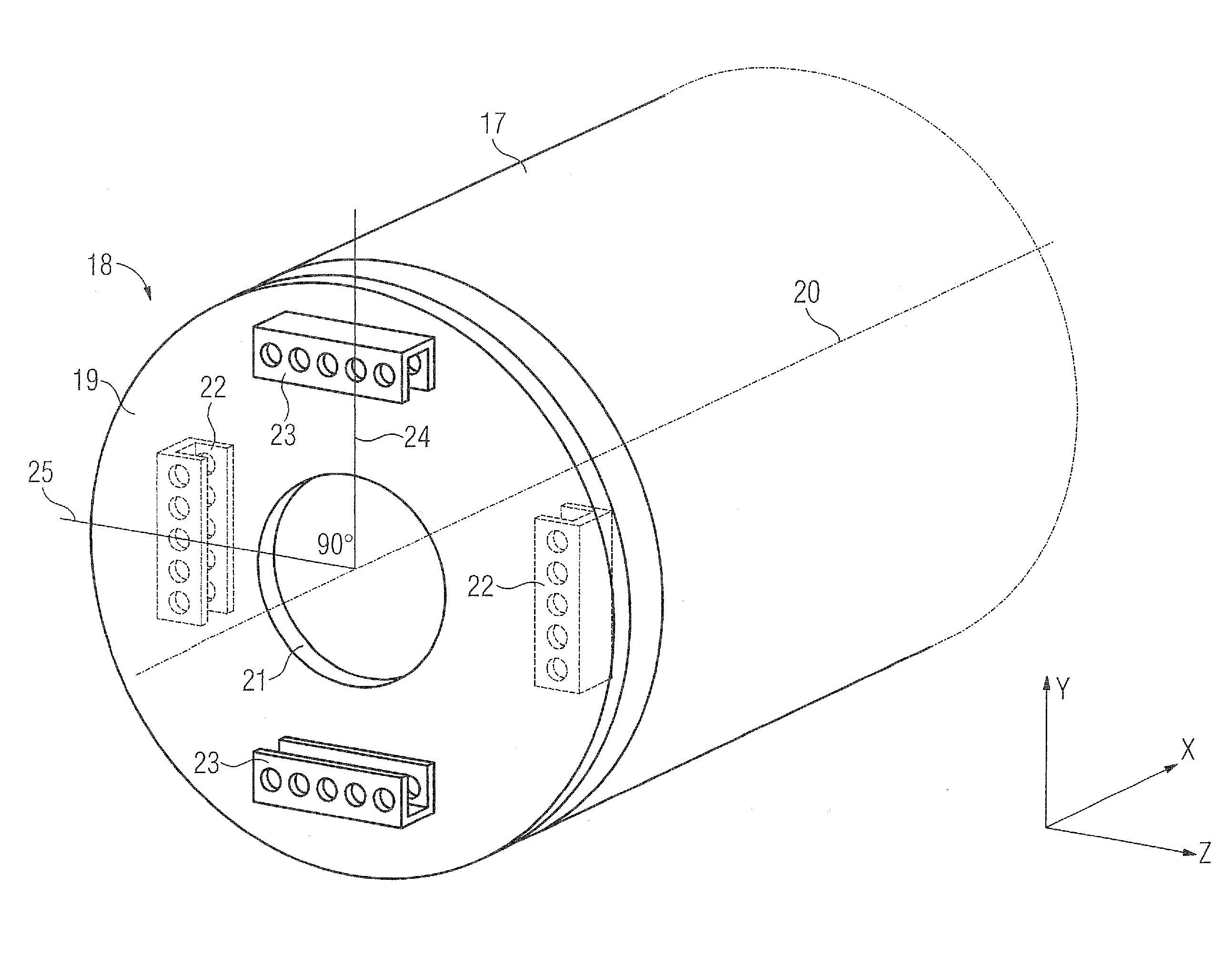
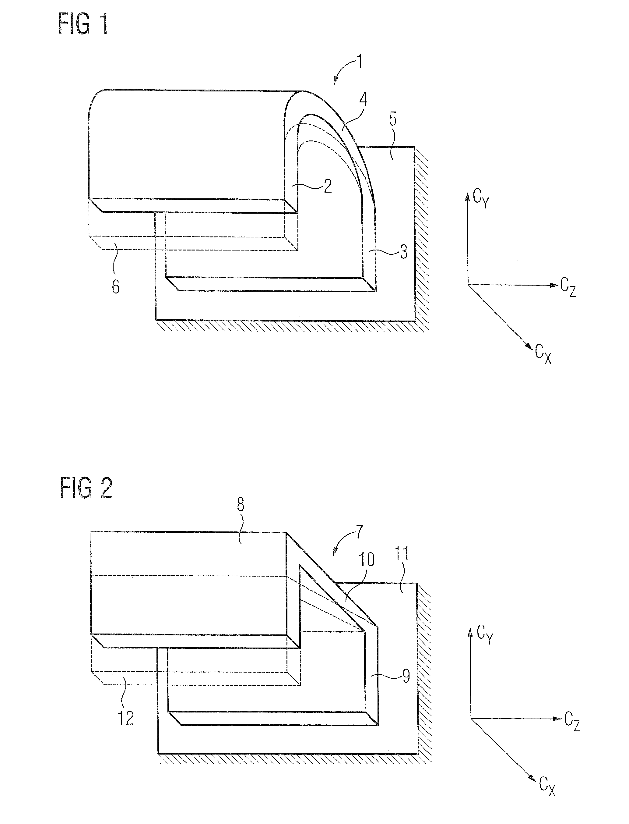
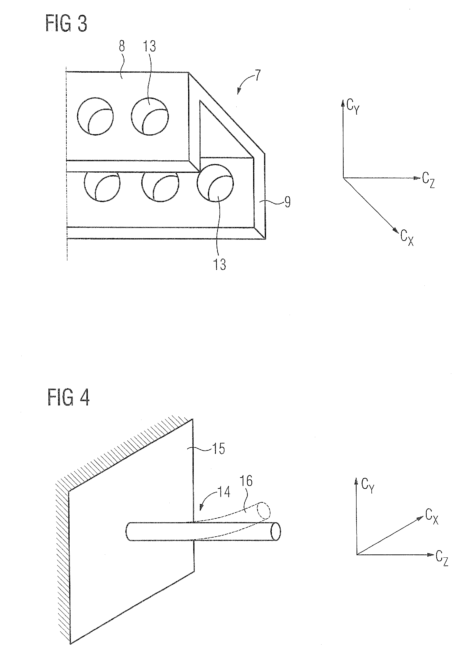
[0027]The present invention is based on the notion of constructing a torque-support device such that as great as possible rotational rigidity will occur around the motor's axis of rotation and as little and as possible translational rigidity will occur with respect to the stator. What are suitable for achieving the relevant objective are structural elements whose rigidity Cx...


PUM


Abstract

An electric machine for installation to a retaining device includes a stator having an axis, and a torque-support device for supporting the stator against the retaining device to prevent a turning movement around the axis. The torque-support device has an intermediate element, at least two holding support elements for providing support against the retaining device, and at least two stator support elements for providing support against the stator. The holding support elements and the stator support elements possess each a greater rigidity in a circumferential direction in relation to the axis than in any other spatial direction.

Description

CROSS-REFERENCES TO RELATED APPLICATIONS[0001]This application claims the priority of European Patent Application, Serial No. EP 10014824, filed Nov. 22, 2010, pursuant to 35 U.S.C. 119(a)-(d), the content of which is incorporated herein by reference in its entirety as if fully set forth herein.BACKGROUND OF THE INVENTION[0002]The present invention relates to an electric machine that can be mounted in or on a retaining device, for example a machine frame.[0003]The following discussion of related art is provided to assist the reader in understanding the advantages of the invention, and is not to be construed as an admission that this related art is prior art to this invention.[0004]If, for example, a torque motor is to drive a separately mounted work machine without a coupling connection on the shaft side, then over-determined bearing will occur. Over-determined bearing of such kind can be successfully avoided by using torque supports that absorb the stator's reaction torque and duct...

Claims


Application Information

Patent Timeline
IPC IPC(8): H02K5/22
CPCH02K1/185H02K5/24H02K5/15
Inventor FROHNAPFEL, MICHAELGEORG, KLAUSHASCHKA, MARKUS STEPHANWAIDER, SEBASTIAN
Owner SIEMENS AG
Why Eureka
Try Eureka