Pulley device, in particular for tensioning idler or runner roller
Active Publication Date: 2020-08-13
AB SKF
View PDF5 Cites 6 Cited by
Summary
Abstract
Description
Claims
Application Information
AI Technical Summary
This helps you quickly interpret patents by identifying the three key elements:
Problems solved by technology
Method used
Benefits of technology
Benefits of technology
The goal of the invention is to create a pulley that is easy to install, rigid, and designed to prevent wear on the belt. Additionally, it should efficiently support the belt.
Problems solved by technology
A major disadvantage of this pulley is that an annular recess is formed on the outer portion adapted to support the belt when the male and female parts are fastened together.
There is therefore a risk of an early wear of the belt.
However, the pulley can still be deformed under heavy loads.
Method used
Image
Click on the blue label to locate the original text in one second.
Reading with bidirectional positioning of images and text.
Examples
first embodiment
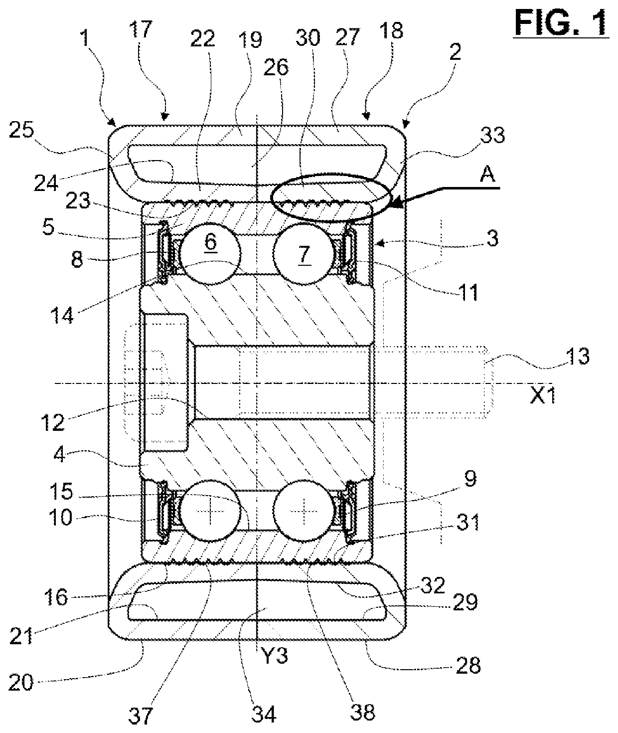
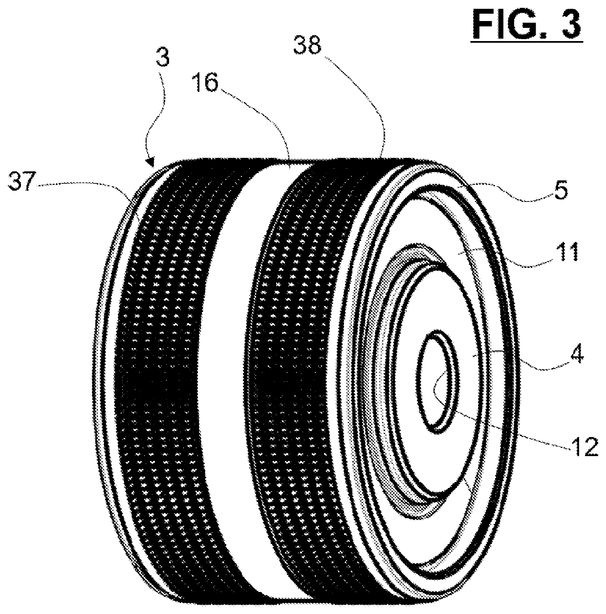
[0058]According the invention, the outer cylindrical surface 16 of outer ring 5 is provided with two annular grip surface portions 37, 38.
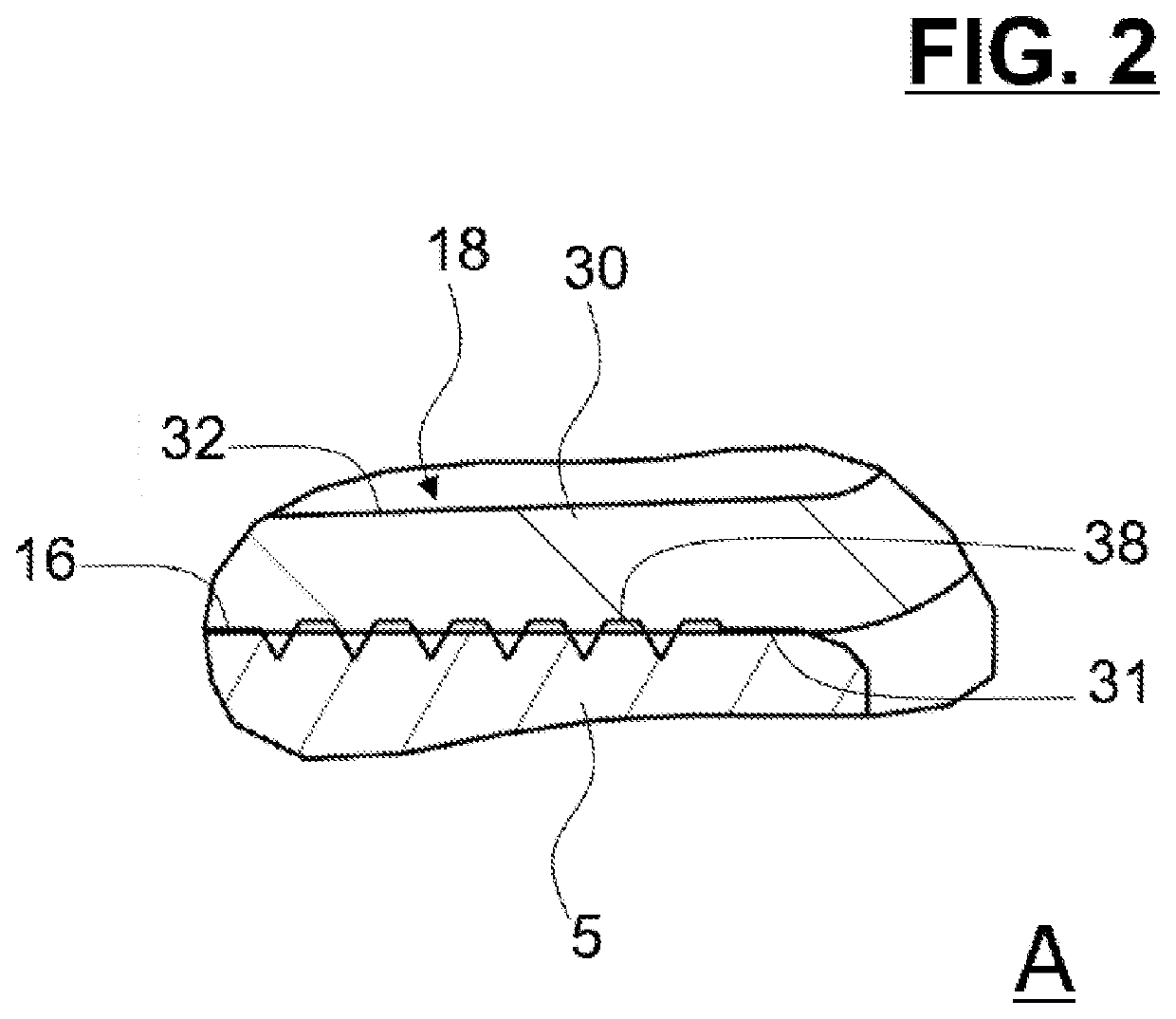
[0059]As illustrated in FIGS. 2 and 3, grip surface portions 37, 38 comprise each a plurality of indentations and recesses. Advantageously, the pitch of indentations and recesses is comprised between 0.1 and 1 mm.
[0060]Advantageously, the indentations and recesses of grip surface portions 37, 38 have a criss-cross pattern, a straight-line pattern, or any other suitable shape.
[0061]The grip surface portions 37, 38 are advantageously manufactured by a knurling process, with a knurling tool.
[0062]The outer cylindrical surface 16 comprises a first grip surface portion 37 on a first axial side, and a second grip surface portion 38 on a second axial side.
[0063]The first grip surface portion 37 extends axially on 70% of the axial length of inner cylindrical surface 23 of inner cylindrical portion 22 of first pulley part 17. Inner cylindrical surface 23 a...
second embodiment
[0067]the invention is illustrated in FIGS. 4 to 6.
[0068]The inner cylindrical surfaces 23, 31 of inner cylindrical portions 22, 30 of pulley parts 17, 18 are each provided with annular grip surface portions 39, 40.
[0069]As illustrated in FIGS. 5 and 6, grip surface portion 39 of first pulley part 17 comprises a plurality of indentations and recesses. Similarly, grip surface portion 40 of second pulley part 18 also comprises a plurality of indentations and recesses.
[0070]The grip surface portions 39, 40 are advantageously manufactured by a knurling process, with a knurling tool.
[0071]Inner cylindrical surface 23 of first pulley part 17, and more particularly the grip surface portion 39, and outer cylindrical surface 16 are in interference fit. Grip surface portion 39 increases the surface roughness of inner cylindrical surface 23 and permits to limit any relative axial displacement between first pulley part 17 and outer ring 5. Similarly, inner cylindrical surface 31 of second pulle...
PUM
Abstract
A pulley device provides a pulley, and a bearing. The pulley has at least one C-shaped pulley part having an inner portion mounted on the bearing, an outer portion having an outer cylindrical surface dedicated to interact with a belt or a chain, and an intermediate portion extending substantially radially between axial ends of inner and outer portions on one axial side of pulley device. A grip surface portion is provided to one surface among the outer cylindrical surface of the outer ring and the inner cylindrical surface of the inner cylindrical portion of the pulley part, the grip surface portion including a plurality of indentations and recesses.
Description
CROSS-REFERENCE TO RELATED APPLICATIONS[0001]This application claims priority to German Patent Application no. 102019201751.7, filed Feb. 11, 2019, the contents of which are fully incorporated herein by reference.TECHNICAL FIELD OF THE INVENTION[0002]The present invention relates to the field of pulley devices for tensioning idlers or runner rollers designed to interact with a chain or a belt, for example a distribution belt of an internal combustion engine of a vehicle.BACKGROUND OF THE INVENTION[0003]Such rollers are usually used to keep a constant tension on the belt or chain in a determined range or to locally modify the path taken by the chain or belt. These are called respectively tensioning idlers or runner rollers. In runner rollers, the pulley is mounted so as to rotate on a screw or a spindle by means of a rolling bearing, the roller then being attached directly or indirectly to the engine block or to an element of a tensioning idler device, for example an articulated arm ...
Claims
Application Information
Patent Timeline
Application Date:The date an application was filed.
Publication Date:The date a patent or application was officially published.
First Publication Date:The earliest publication date of a patent with the same application number.
Issue Date:Publication date of the patent grant document.
PCT Entry Date:The Entry date of PCT National Phase.
Estimated Expiry Date:The statutory expiry date of a patent right according to the Patent Law, and it is the longest term of protection that the patent right can achieve without the termination of the patent right due to other reasons(Term extension factor has been taken into account ).
Invalid Date:Actual expiry date is based on effective date or publication date of legal transaction data of invalid patent.

