Shaft-Seal Device for High-Temperature Fluid

a high-temperature fluid and shaft seal technology, applied in the direction of engine seals, mechanical apparatus, engine components, etc., can solve the problems of secondary seal function, o-ring deterioration, deterioration of the suppleness of the stationary scaling ring, etc., and achieve good mechanical seal function.

Inactive Publication Date: 2012-12-27
NIPPON PILLAR PACKING CO LTD +1
View PDF26 Cites 3 Cited by
  • Summary
  • Abstract
  • Description
  • Claims
  • Application Information

AI Technical Summary

Benefits of technology

[0009]The present invention is made in view of the facts described above, and an object of the present invention is to provide a shaft-seal device for high-temperature fluid in wh...

Problems solved by technology

However, the reality is that the mechanical seal members, to which the high-temperature fluid that is the sealed fluid comes in contact directly, cannot be cooled sufficiently by the cooling means described above, causing various troubles.
For example, when high-temperature fluid comes in contact with an O...

Method used


Image

  • Shaft-Seal Device for High-Temperature Fluid
  • Shaft-Seal Device for High-Temperature Fluid
  • Shaft-Seal Device for High-Temperature Fluid

Examples


Embodiment Construction

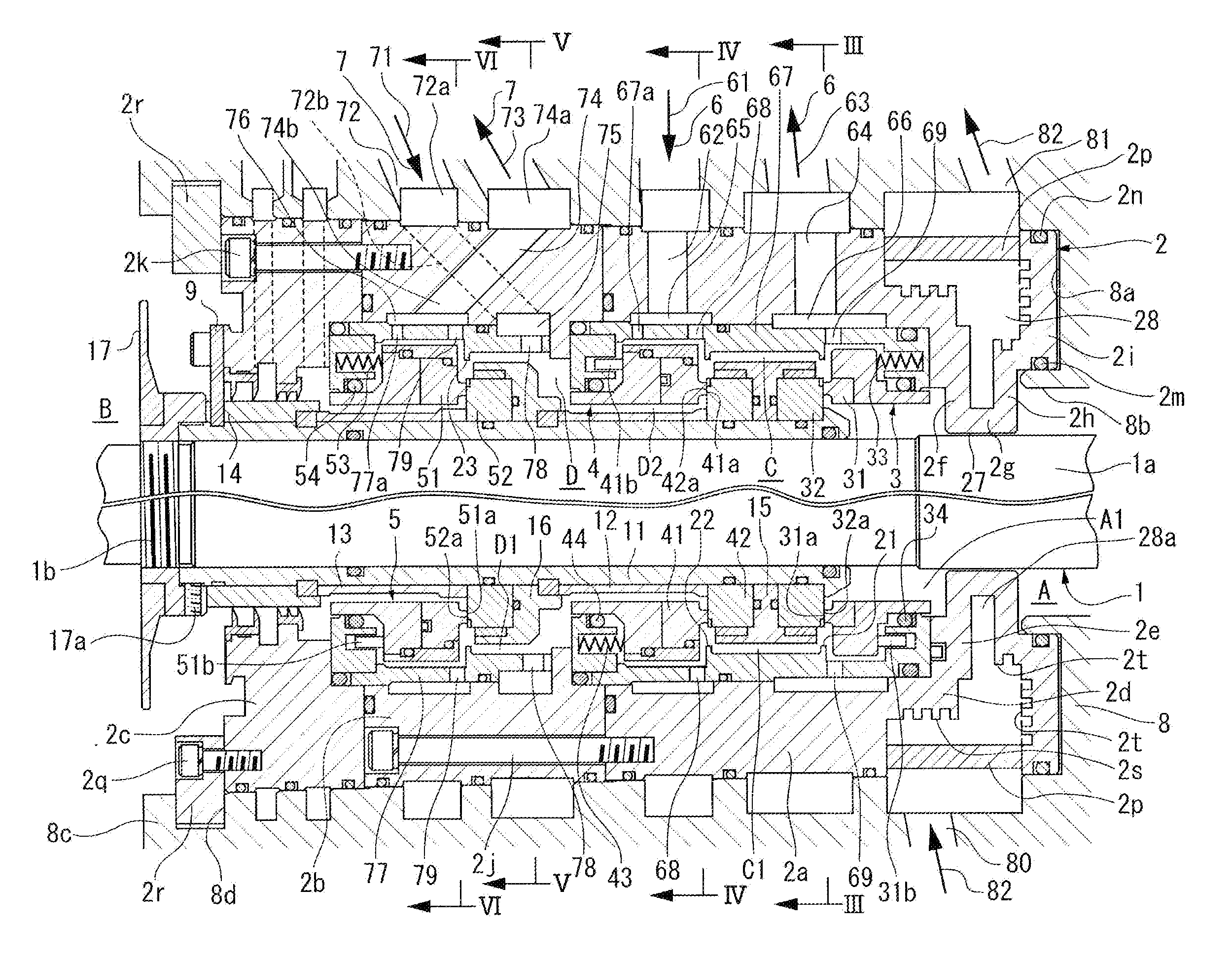
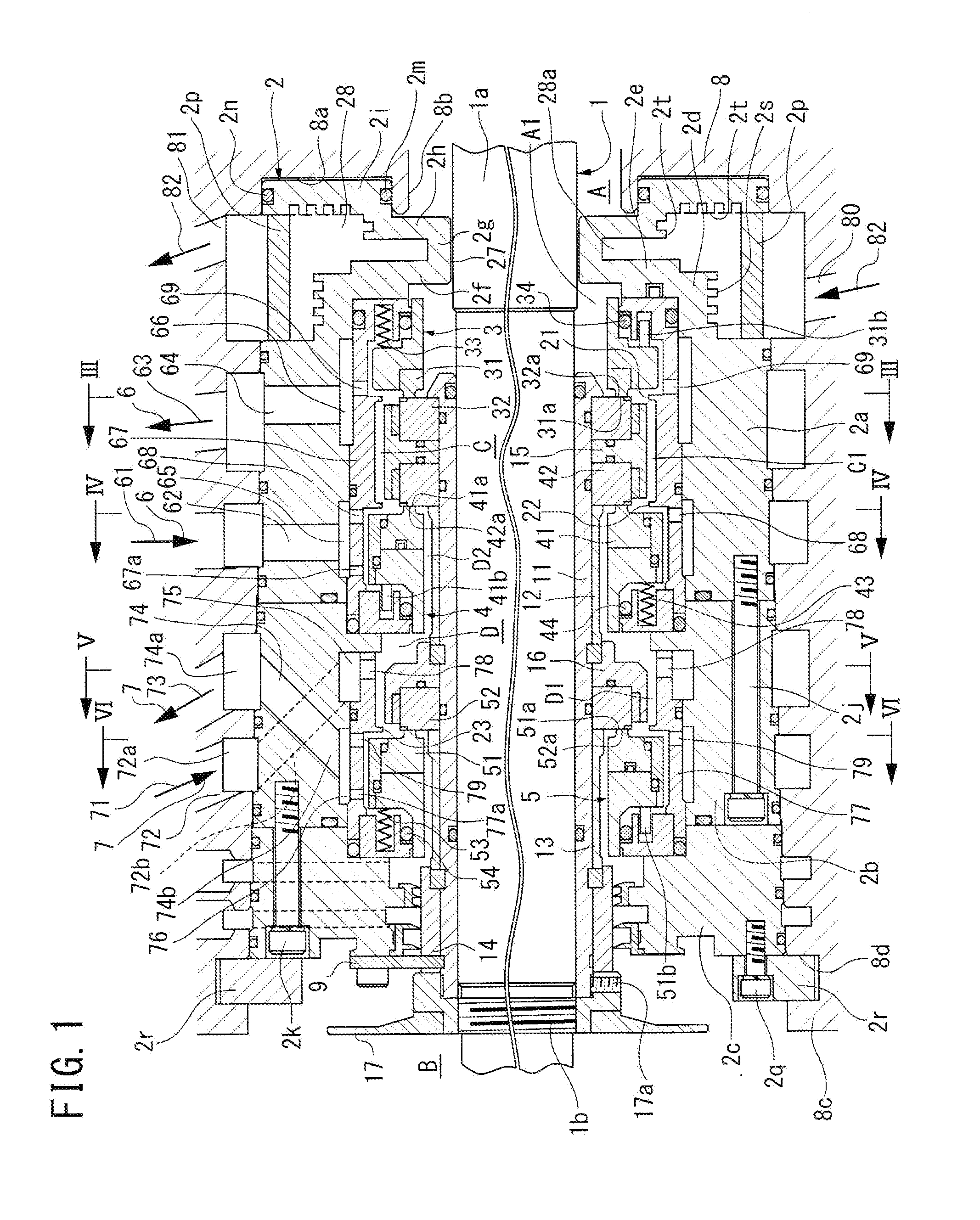
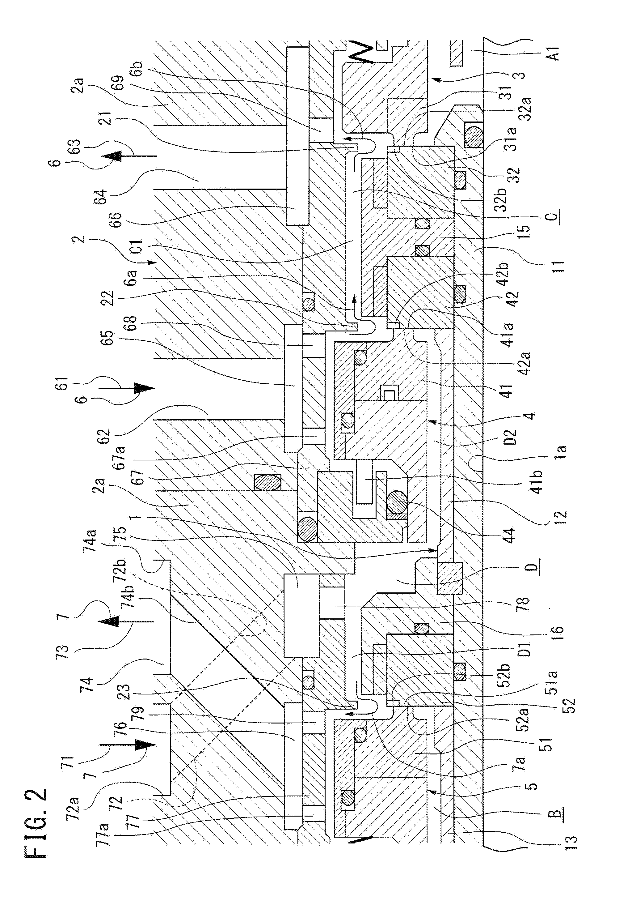
[0076]FIG. 1 is a vertically-sectioned side view showing an embodiment of the shaft-seal device for high temperature fluid according to the present invention, FIG. 2 is a detailed and enlarged view of its essential portion, FIG. 3 is a front vertical cross-sectional view along the III-III line of FIG. 1, FIG. 4 is a front vertical cross-sectional view along the IV-IV line of FIG. 1, FIG. 5 is a front vertical cross-sectional view along the V-V line of FIG. 1, and FIG. 6 is a front vertical cross-sectional view along the VI-VI line of FIG. 1.

[0077]The shaft-seal device for high-temperature fluid shown in FIG. 1 is a rotation apparatus that handles treating high-temperature fluid (for example, high-temperature gas of high pressure) and, especially, it is a shaft-seal device of the second aspect of the present invention which is compatible with a high PV value that is used in a rotation apparatus (such as vapor compressors used in nuclear electricity generation systems) in which the ro...


PUM


Abstract

A shaft-seal device for high-temperature fluid including a seal case (2) formed as a metallic cylindrical structure of a single unit and comprised of a main body portion (2a, 2b, 2c), first and second holding portions (2d, 2e), first and second partition portions (2f, 2h), a channel formation portion (2g) forming a minute annular channel (27) with the outer circumference surface of a rotary shaft (1), and an o-ring holding portion (2i). The seal case is installed in an apparatus housing (8) with first and second o-rings (2m, 2n) in between. The intra-seal case region (A1), in which sealing rings (31, 32, 41, 42, 51, 52) of mechanical seals (3, 4, 5) are provided, and the high-temperature fluid region, which is an intra-apparatus housing region (A), are partitioned by a cooling chamber (28) into and from which coolant (82) is supplied and discharged via feed/discharge coolant paths (80, 81).

Description

BACKGROUND OF THE INVENTION[0001]1. Field of the Invention[0002]The present invention relates to a shaft-seal device for high-temperature fluid used in rotating machines (for example, a steam compressor, a compressor, a blower, a pump, or a stirrer that is used in a nuclear power generation system, among others) that deals with high-temperature fluid such as high-temperature steam and boiler water.[0003]2. Description of the Related Art[0004]In this type of shaft-seal device, as a sealing means, a mechanical seal is used, in which the sealing performance is provided by the relative rotation effect of the sealing end-faces that are the facing end-faces of a rotational sealing ring fixed to a rotary shaft, and a stationary sealing ring held to a seal case with an O-ring interposed so as to be movable in the axial direction. Normally, to prevent heat damage of the mechanical seal components, it is devised so that the components, such as the sealing ring, are cooled by setting up a wate...

Claims


Application Information

Patent Timeline
IPC IPC(8): F16J15/38F16J15/34
CPCF16J15/3404F16J15/40F16J15/3484
Inventor HASHIMOTO, TAIJIHU, TAOOKUMACHI, EIJININOMIYA, MASANOBU
Owner NIPPON PILLAR PACKING CO LTD
Why Eureka
Try Eureka