User adjustable coupling device or hinge

a technology of coupling device and user, which is applied in the direction of lighting support device, washstand, stove or range, etc., can solve the problems of narrow problems that do not readily adapt, aforementioned hinges, limited to specific components or devices that minimize flexibility and usefulness, and solve limited, fast and efficient effect of adding or removing cooking supports

Inactive Publication Date: 2013-02-07
JACQUES DAVID A +2
View PDF57 Cites 14 Cited by
  • Summary
  • Abstract
  • Description
  • Claims
  • Application Information

AI Technical Summary

Benefits of technology

[0012]The present invention also provides an outdoor cooking grill or apparatus comprising a heat source area, at lease one vertically oriented spine, at least one cooking support operably connected to a spine and adapted for rotatable and vertical movement above the heat source area, and a quick-release mechanism attached or attachable to the cooking support that allows a user to easily, quickly and efficiently add or remove the cooking support from the spine without hand tools. The cooking support further comprises a plurality of cooking surfaces to increase the total cooking surface of the apparatus or types of cooking surfaces.
[0013]The heat source area may define a perimeter that impedes horizontal movement of the source while allowing heat to vertically rise and warm the cooking surface or surfaces. The spine is adapted to engage a cooking support and hold it in place along a vertical length of the spine. The coupling device or hinge is adapted to engage the spine and / or the collar and allows a user to add or remove cooking supports and surfaces without tools. The hinge also allows the cooking support and surface to rotate around the vertical axis of the spine allowing the user to rotate the cooking support and surface over or away from the heat source.

Problems solved by technology

Most types, however, solve limited, narrow problems that do not readily adapt to other purposes.
All the aforementioned hinges, however, are limited to specific components or devices that minimize their flexibility and usefulness.
The aforementioned outdoor barbecue grills and others in the prior art typically offer limited features.

Method used


Image

  • User adjustable coupling device or hinge
  • User adjustable coupling device or hinge
  • User adjustable coupling device or hinge

Examples


Embodiment Construction

[0027]In the following detailed description, the accompanying drawings show by way of illustration specific embodiments or examples. These embodiments may be combined, other embodiments may be utilized, and structural, logical, and procedural changes may be made without departing from the spirit and scope of the present invention. The following detailed description is, therefore, not to be taken in a limiting sense, and the scope of the present invention is defined by the appended claims and their equivalents.

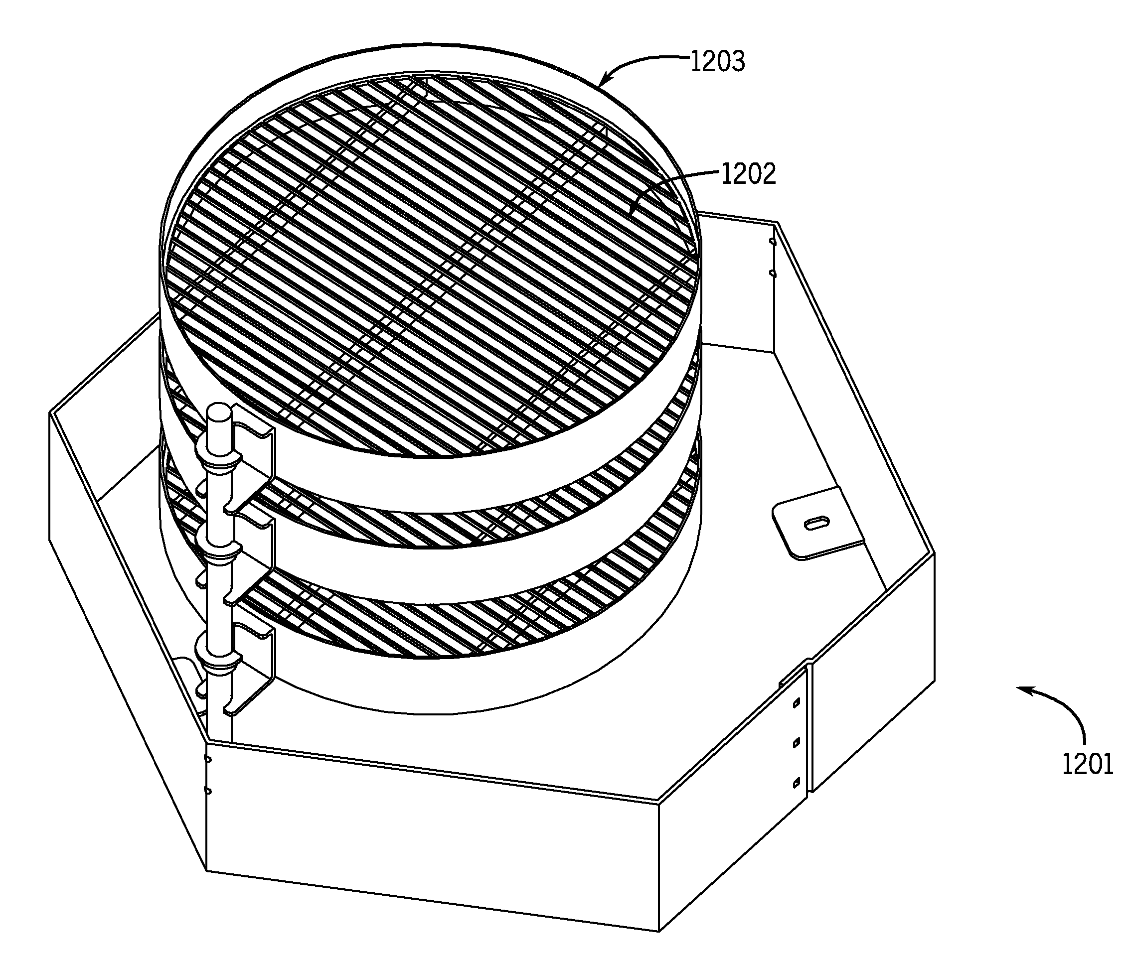
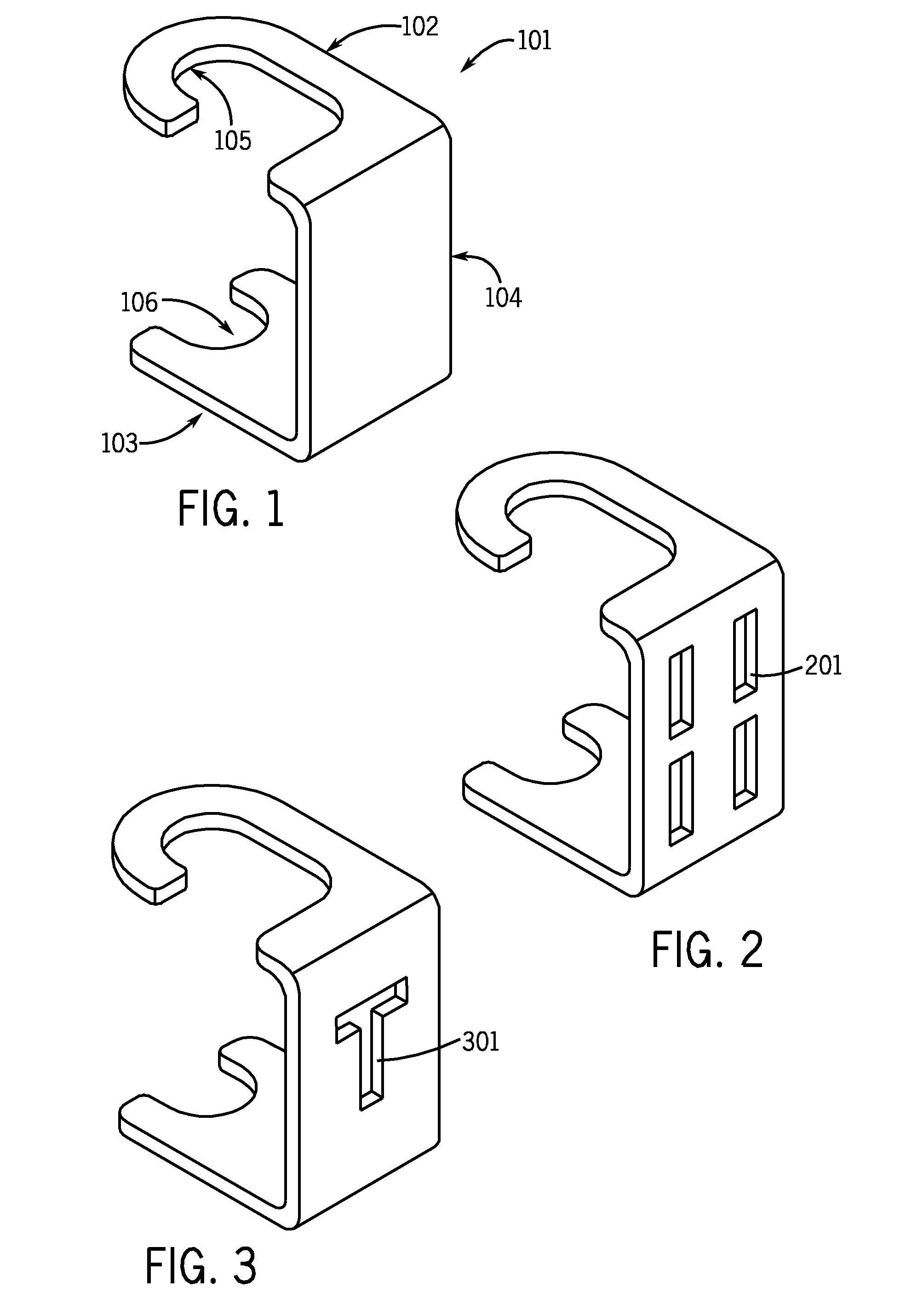
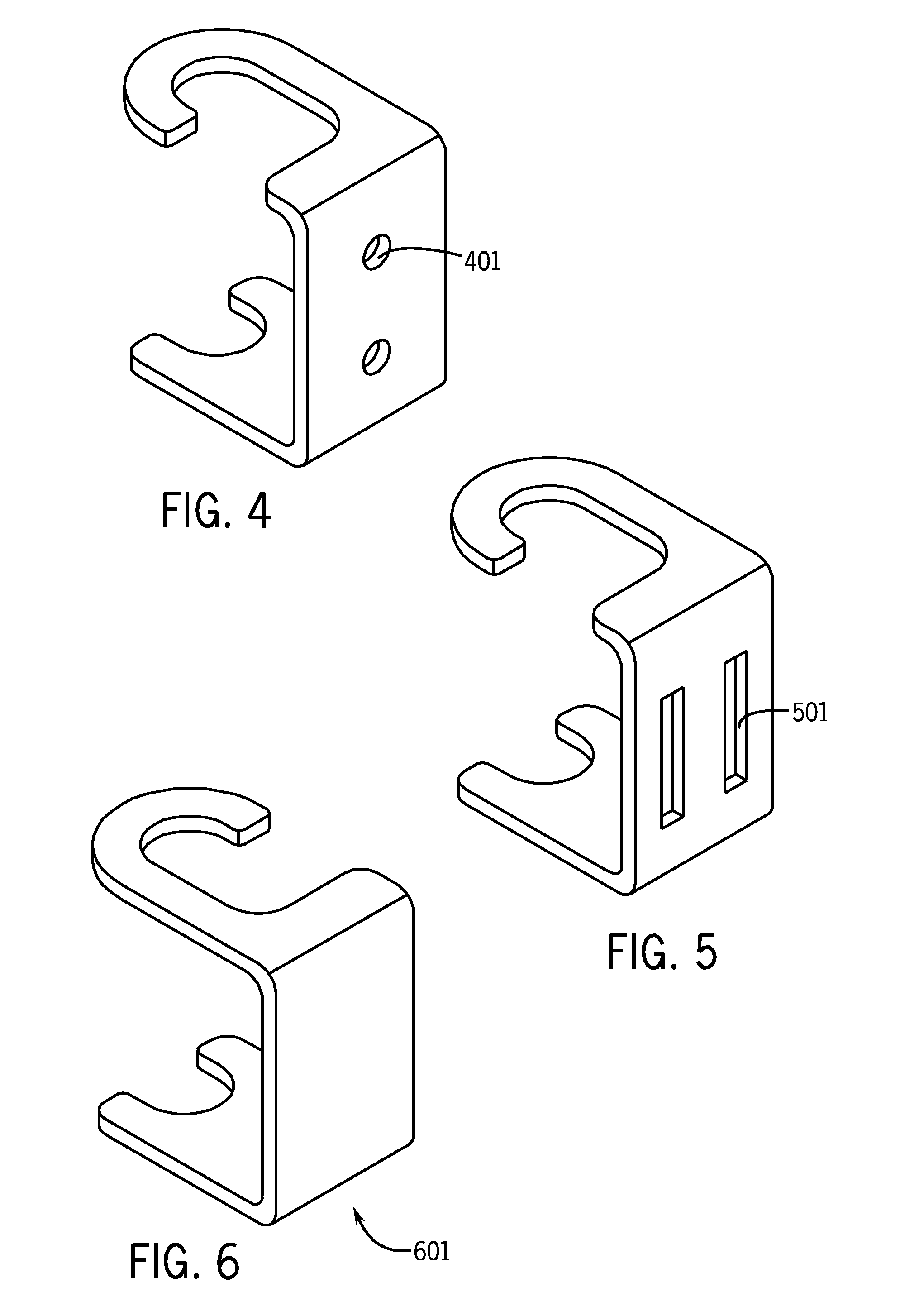
[0028]An embodiment of the device or apparatus comprises steel, although other rigid materials like plastic, wood or other metals like cast iron may be suitable. An embodiment of the coupling device or hinge comprises a C-shaped article 101601701 further comprising upper 102 and lower horizontal 103 brackets integrated with a vertical support brace 104, wherein the two horizontal brackets are adapted to engage a collar 1001 mounted on a spine 801 or a flange 902 incorporated in...


PUM


Abstract

A user adjustable coupling device or hinge adapted to be attachable to a spine is disclosed. The device or hinge comprises a curved, hook end on a horizontally oriented upper bracket, a vertically oriented support brace, and a curved, oval-shaped end on a horizontally oriented lower bracket that gives the hinge a C-shaped configuration. The hook and oval ends allow the hinge to be quickly and easily attached and removed from the spine without the use of tools. The coupling device or hinge may be utilized in an outdoor cooking apparatus. The apparatus comprises an enclosed area defining a heat containment structure, a spine operably connected to the heat containment structure, a collar operably connected to the spine, and at least one cooking support attached or attachable to the coupling device or hinge.

Description

BACKGROUND OF THE INVENTION[0001]1. Field of the Invention[0002]The present invention relates to a coupling device or hinge that provides quick and simple connection and disconnection to and from a spine, user adjustable positioning of the device or hinge along a length of the spine, wide-angle rotatable movement of the device or hinge around an axis of the spine, and quick and simple connection and disconnection of a component to the coupling device or hinge.[0003]2. Description of the Prior Art[0004]Coupling devices or hinges are well known and many types exist in the prior art. Most types, however, solve limited, narrow problems that do not readily adapt to other purposes. For example, U.S. Pat. No. 1,145,759 to Dwyer discloses a hinge for use on storm doors, windows, or ordinary doors with a removable pintle. U.S. Pat. No. 3,059,271 to Ericsson discloses a hinge for supporting a door on a frame to swing about a fixed axis between open and closed positions to permit easy removal ...

Claims


Application Information

Patent Timeline
Patent Type & Authority Applications(United States)
IPC IPC(8): A47J33/00F16C11/04
CPCA47J33/00
Inventor JACQUES, DAVID A.JACQUES, MARK L.MCMULLEN, MARK D.
Owner JACQUES DAVID A
Why Eureka
Try Eureka