

Bi-stable spring with flexible display
a technology of flexible display and spring, which is applied in the field of portable electronic devices, can solve the problem that the accessories of electronic devices are not easy to wear, and achieve the effect of improving the wearability of the devi
- Summary
- Abstract
- Description
- Claims
- Application Information
AI Technical Summary
Benefits of technology
Problems solved by technology
Method used
Image

Examples
Embodiment Construction
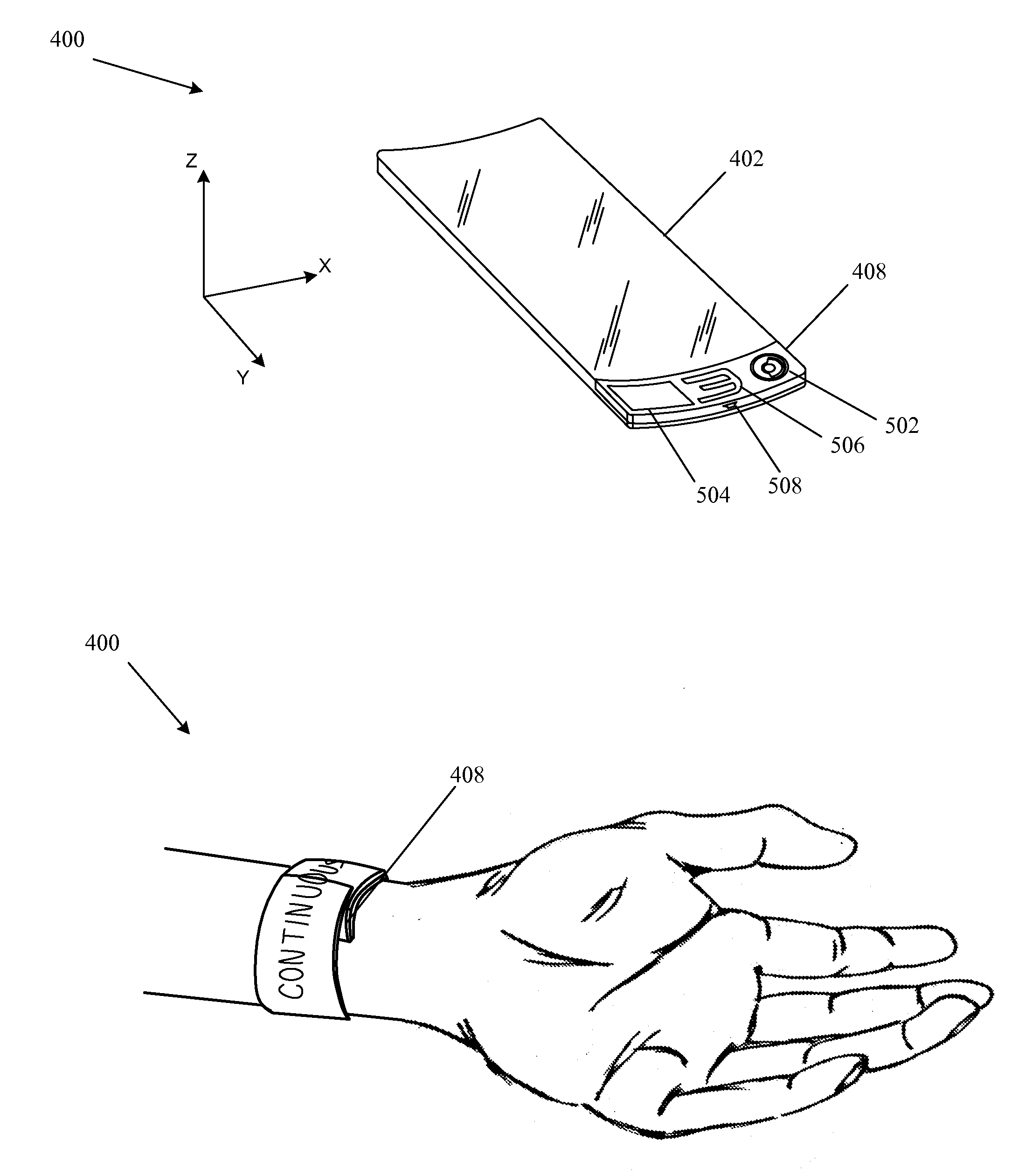
[0002]The described embodiments relate generally to portable electronic devices. In particular methods for expanding the functionality of electronic devices are disclosed.
[0003]2. Related Art
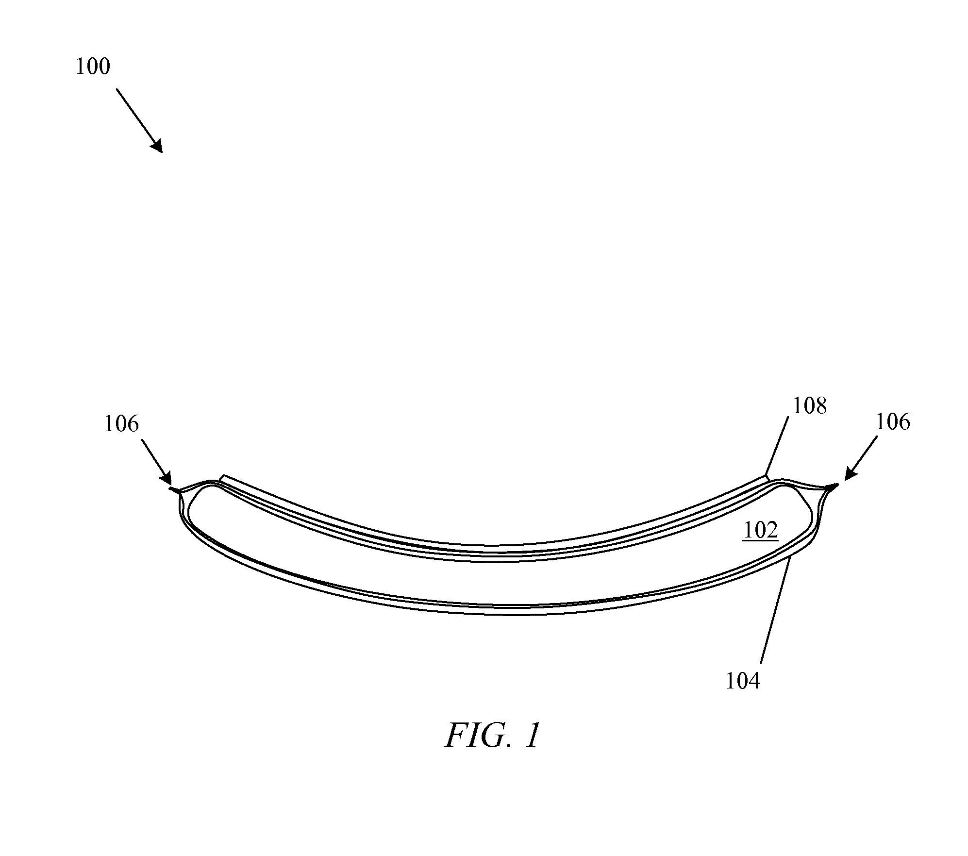
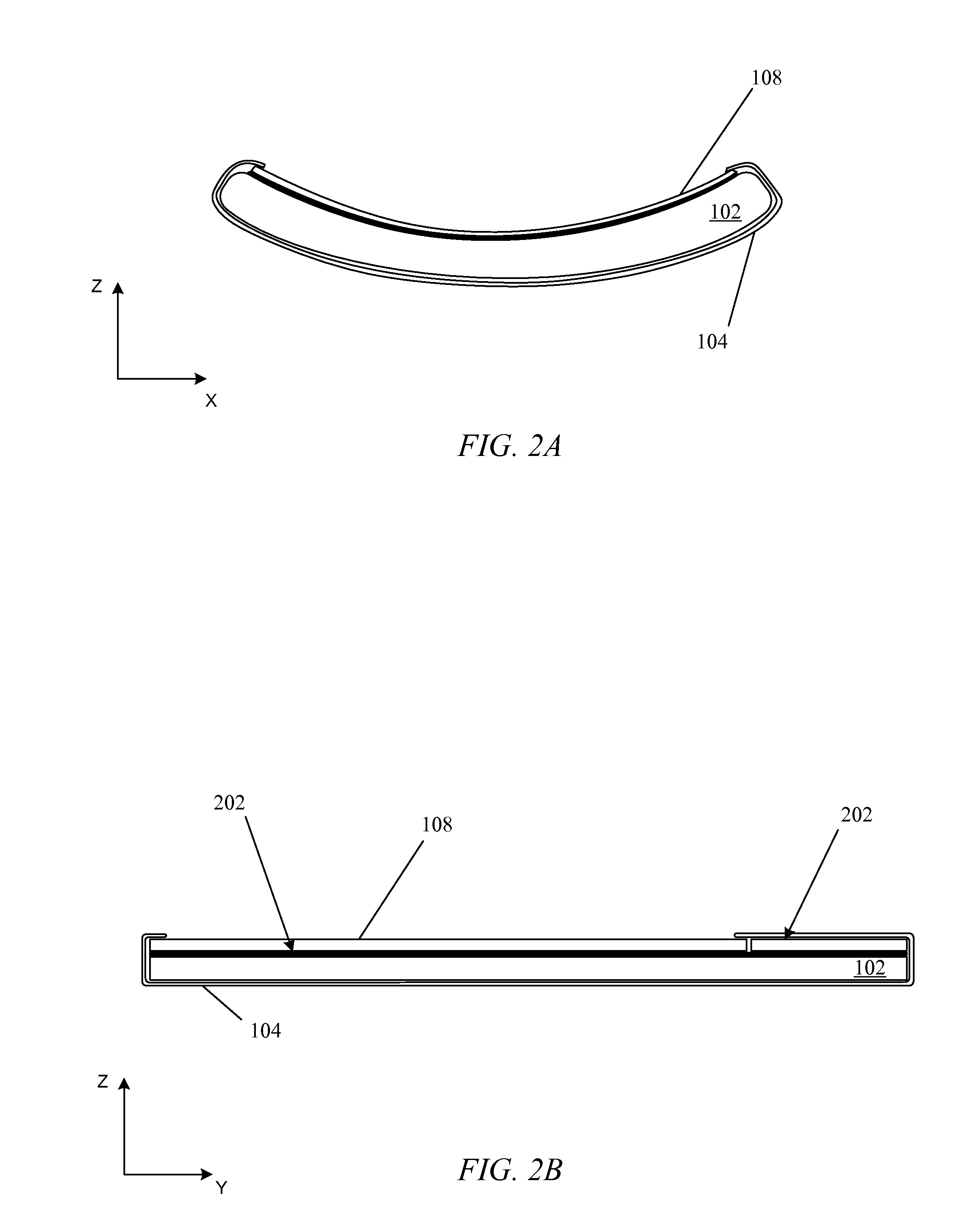
[0004]Bi-stable springs have two equilibrium positions. This allows a device with a bi-stable spring to assume two distinct configurations. The most recent widespread use of such a device was the slap bracelet, also called the slap wrap. The slap bracelet consists of layered flexible steel bands sealed within a fabric cover. Typical slap bracelets are roughly one inch in width by nine inches in length. In a first equilibrium position they can be flat. The second equilibrium is typically reached by slapping the flat embodiment across the wrist, at which point the bracelet curls around the wrist and stays relatively secure in a roughly circular position. The slap bracelet has been used primarily as a decorative bracelet; however, other uses have included for example keeping a pant leg away from a ...
PUM
 Abstract
Description
Claims
Application Information