
Visual expander

a visual expander and expander technology, applied in the field of touch screen display methods and systems, can solve the problems of reducing the amount of space available for displaying other information to the user, difficult to use, and small features

Active Publication Date: 2006-02-02
APPLE INC
View PDF22 Cites 1134 Cited by
  • Summary
  • Abstract
  • Description
  • Claims
  • Application Information

AI Technical Summary

Benefits of technology

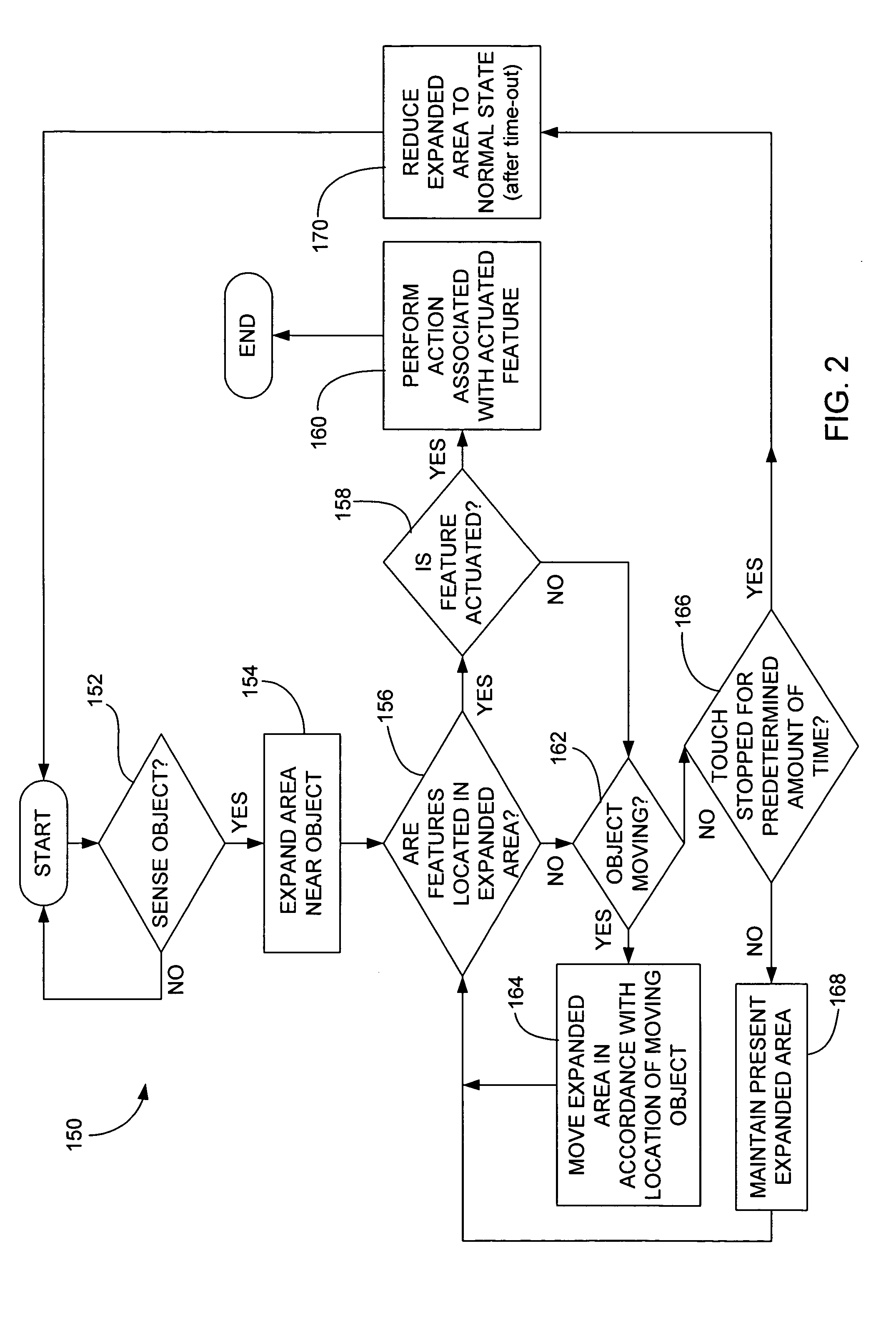
[0012] The invention relates, in another embodiment, to a computer implemented method. The method includes presenting a graphical user interface (GUI). the method also includes sensing an object over the graphical user interface. The method further includes visually expanding an area of GUI near the sensed object. The method additionally includes if the expanded area includes a selectable fea

Problems solved by technology

While touchscreens generally work well, they are difficult to use when features such as buttons, web page links, or UI controls presented on the touch screen display are too small for finger activation, i.e., the finger is too large relative to the button, link or UI controls.
Even if these features could be enlarged to meet minimum human factors requirements, they would adversely reduce the amount of space available for displaying other information to the user.
In fact, in most cases the features are made small due to the limited amount of screen space (especially in handheld devices).
Furthermore, the features typically do not provide the user with any feedback indicating that a finger is located on the feature.
This may make it difficult to determine what feature is being selected.
As a result, the user may incorrectly select a feature.
Moreover, once the size of the features are set, they typically cannot be changed.
This may be difficult for some users such as those who are visually impaired or those with limited coordination.
In addition, the stylus can be lost and it can be aesthetically unpleasing.
For example, the stylus is typically separate from the computing device in which it is used and therefore the stylus can be easily misplaced by the user.
With regards to being aesthetically unpleasing, the computing device typically includes a receptacle, which receives the stylus and which produces unwanted breaks and cracks in the external surface of the computing device.
While virtual magnifying glasses work well, they are limited.
For example, they typically do not allow features to be manipulated or selected inside the magnified area.
Furthermore, they may not allow text editing therein.
While this works well, the feature has no control over the content presented on the remainder of the screen, i.e., the remaining portions of the screen do not magnify when the cursor is positioned thereover.
It does not work in programs or applications or even web pages.

Method used


Image

  • Visual expander
  • Visual expander
  • Visual expander

Examples


Embodiment Construction

[0030] Embodiments of the invention are discussed below with reference to FIGS. 1-15. However, those skilled in the art will readily appreciate that the detailed description given herein with respect to these figures is for explanatory purposes as the invention extends beyond these limited embodiments.

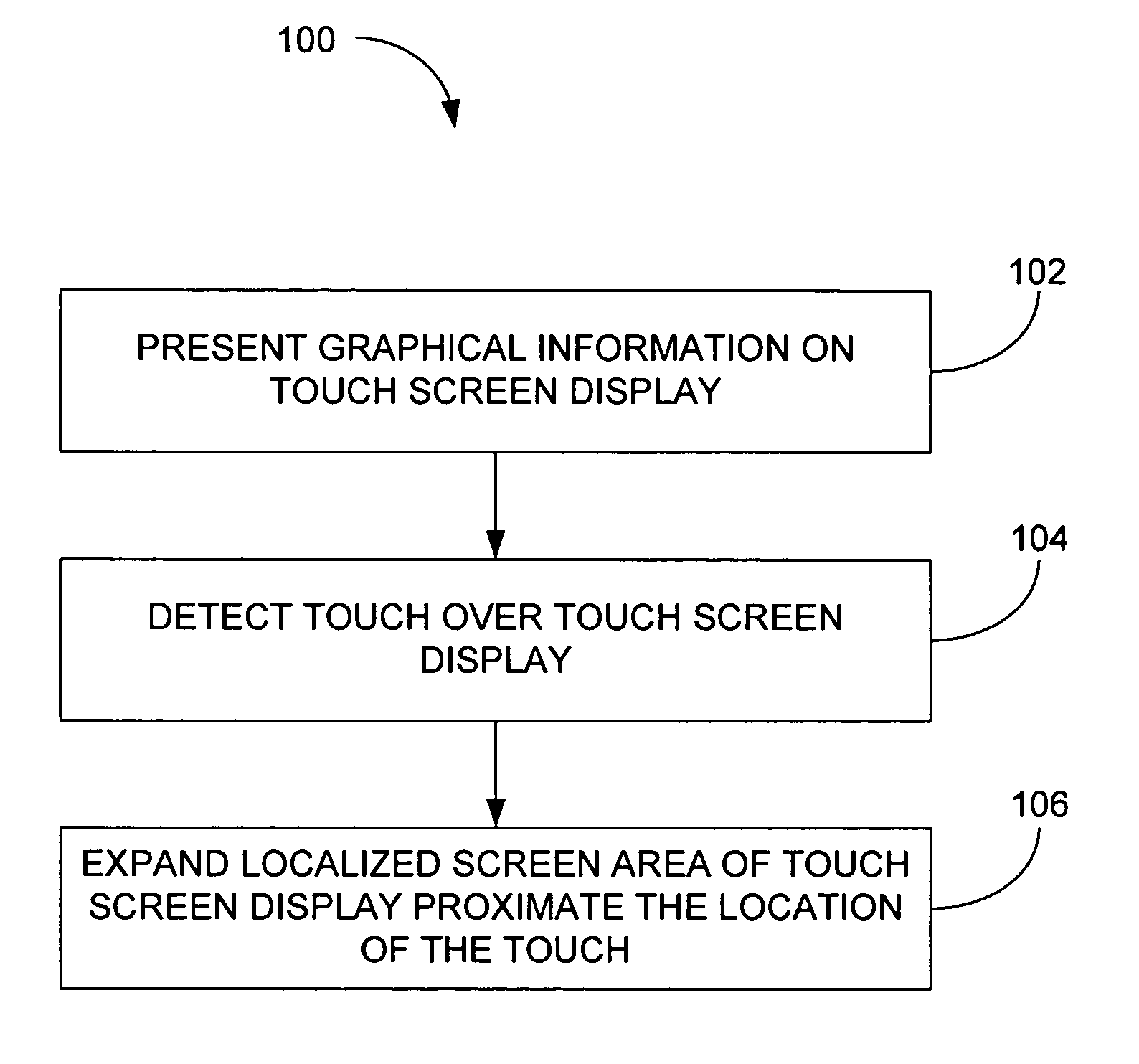
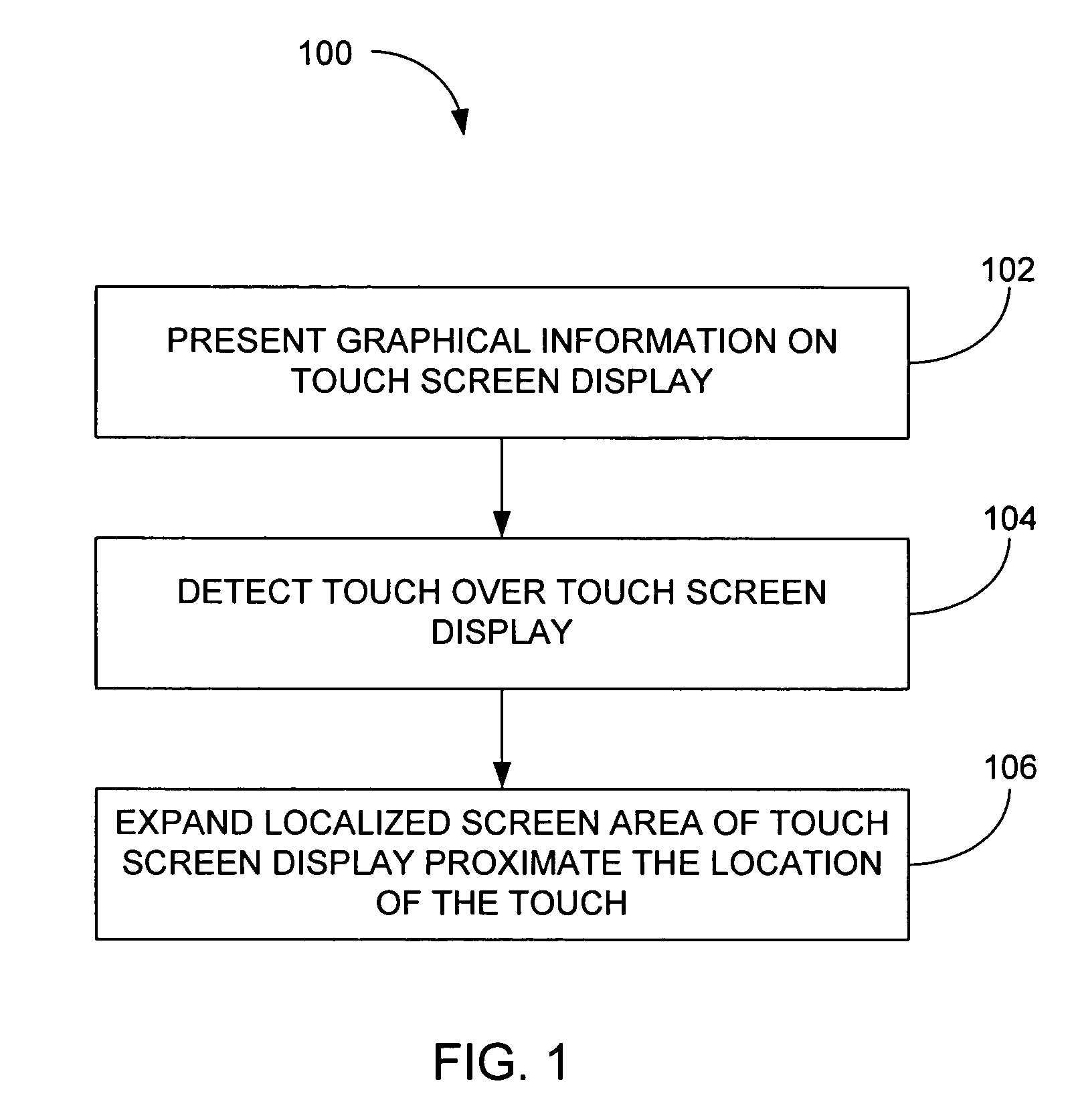
[0031]FIG. 1 is an expansion method, in accordance with one embodiment of the present invention. The method may be implemented on computing devices having a touchscreen display. Touchscreen displays generally consist of a display and a substantially transparent touchscreen that is laid over the display. The display is configured to present graphical information, and the touchscreen is configured to receive touch inputs. The touchscreen may for example be used to perform tracking make selections, issue commands, and controlling interface elements with respect to the graphical information on the display. By way of example, the computing devices may include desktops, laptops, tablets, an...


PUM


Abstract

A computer implemented method for a touchscreen display is disclosed. The method includes presenting graphical information on the touchscreen display. The method further includes detecting a touch over the touchscreen display. The method also includes expanding an area of the touch screen display proximate the location of the touch.

Description

CROSS-REFERENCE TO RELATED APPLICATIONS [0001] This application is claims priority to U.S. Provisional Patent Application No.: 60 / 592,483, filed Jul. 30, 2004, entitled “TOUCH SENSITIVE TECHNIQUES AND INPUT DEVICES,” which is hereby incorporated herein by reference.BACKGROUND OF THE INVENTION [0002] 1. Field of the Invention [0003] The present invention relates generally to methods and systems associated with touch screen displays. More particularly, the present invention relates to expanding graphical and sensitive portions of a touchscreen display. [0004] 2. Description of the Related Art [0005] There exist today many styles of input devices for performing operations in a computer system. The operations generally correspond to moving a cursor and / or making selections on a display screen. By way of example, the input devices may include buttons or keys, mice, trackballs, touch pads, joy sticks, touch screens and the like. Each of these devices has advantages and disadvantages that ...

Claims


Application Information

Patent Timeline
IPC IPC(8): G09G5/00
CPCG06F3/0414G06F2203/04805G06F3/04883G06F3/0416G06F3/0488
Inventor KENNEDY, PETER
Owner APPLE INC
Learn More