Vehicle headlamp

Active Publication Date: 2013-02-28
STANLEY ELECTRIC CO LTD
View PDF4 Cites 16 Cited by
  • Summary
  • Abstract
  • Description
  • Claims
  • Application Information

AI Technical Summary

Benefits of technology

[0012]The presently disclosed subject matter is made to solve at least one of the above problems, and to provide a vehicle headlamp in which the illuminance of the specific point of the low beam can be suppressed while making an illumination gradient gentle around the specific point of the low beam.
[0013]To solve at least one of the above problems, according to an aspect of the presently disclosed subject matter, there is provided a vehicle headlamp for generating a low beam in front of the vehicle, including a light source; a reflector to project light output from the light source; a projection lens provided in front of the reflector to project the light reflected by the reflector and to be incident on the projection lens; a

Problems solved by technology

Thus, the region Pa is excessively dark because the light does not illuminate the region Pa and illumination unevenness with the surrounding region becomes noticeable.
Thus, the region Pa is excessively dark and the illumination unevenness wi

Method used


Image

  • Vehicle headlamp
  • Vehicle headlamp
  • Vehicle headlamp

Examples


Embodiment Construction

[0025]Hereafter, an embodiment of the presently disclosed subject matter is described with reference to the drawings.

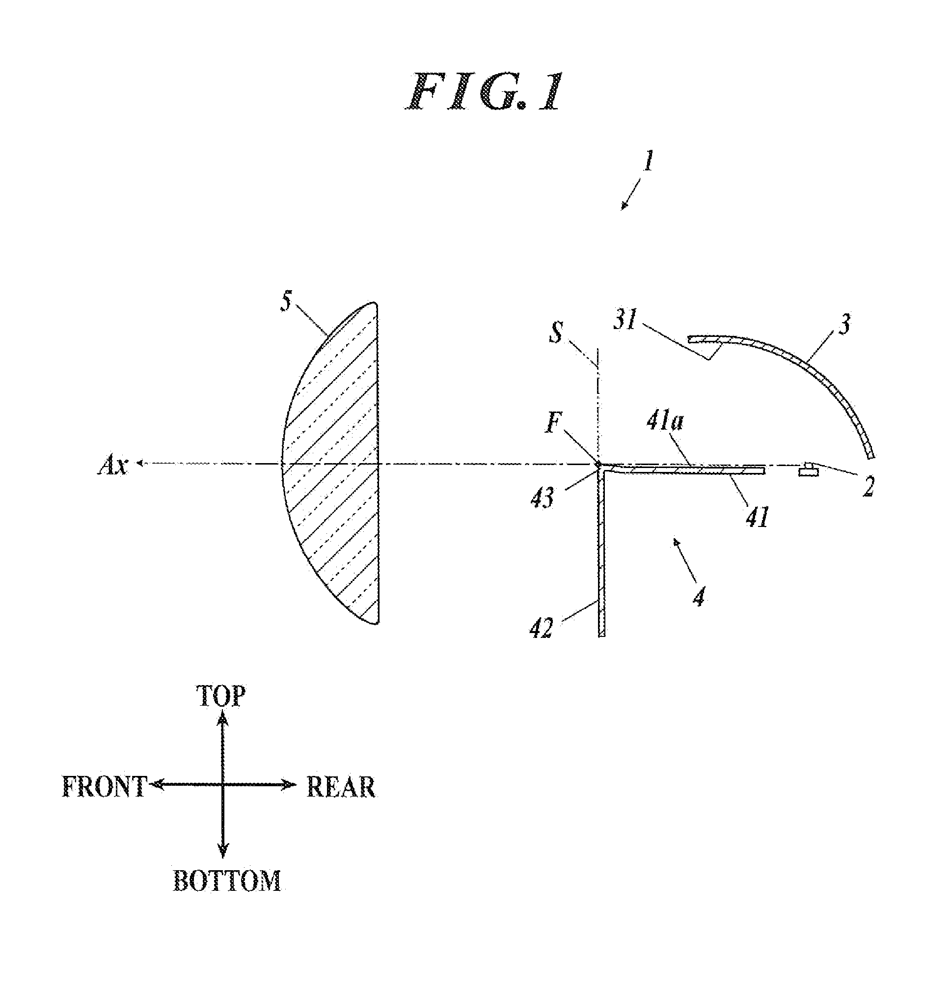
[0026]FIG. 1 is a side cross-sectional view of a vehicle headlamp 1 of the embodiment.

[0027]Here, in the following description, “front”, “rear”, “left”, “right”, “top”, and “bottom” indicate directions viewed from the vehicle headlamp 1 or from a vehicle with which the vehicle headlamp 1 is equipped, and used in correspondence with those in the drawings.

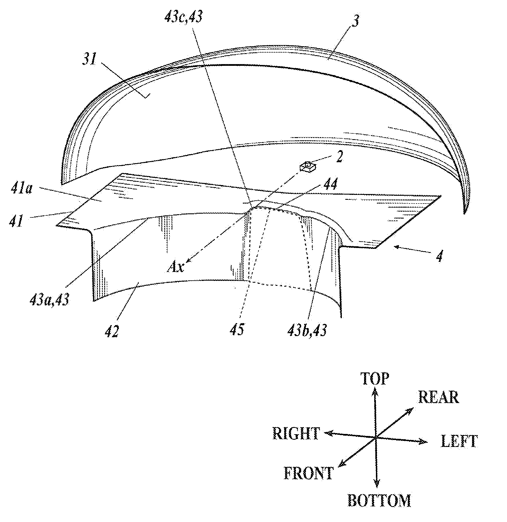
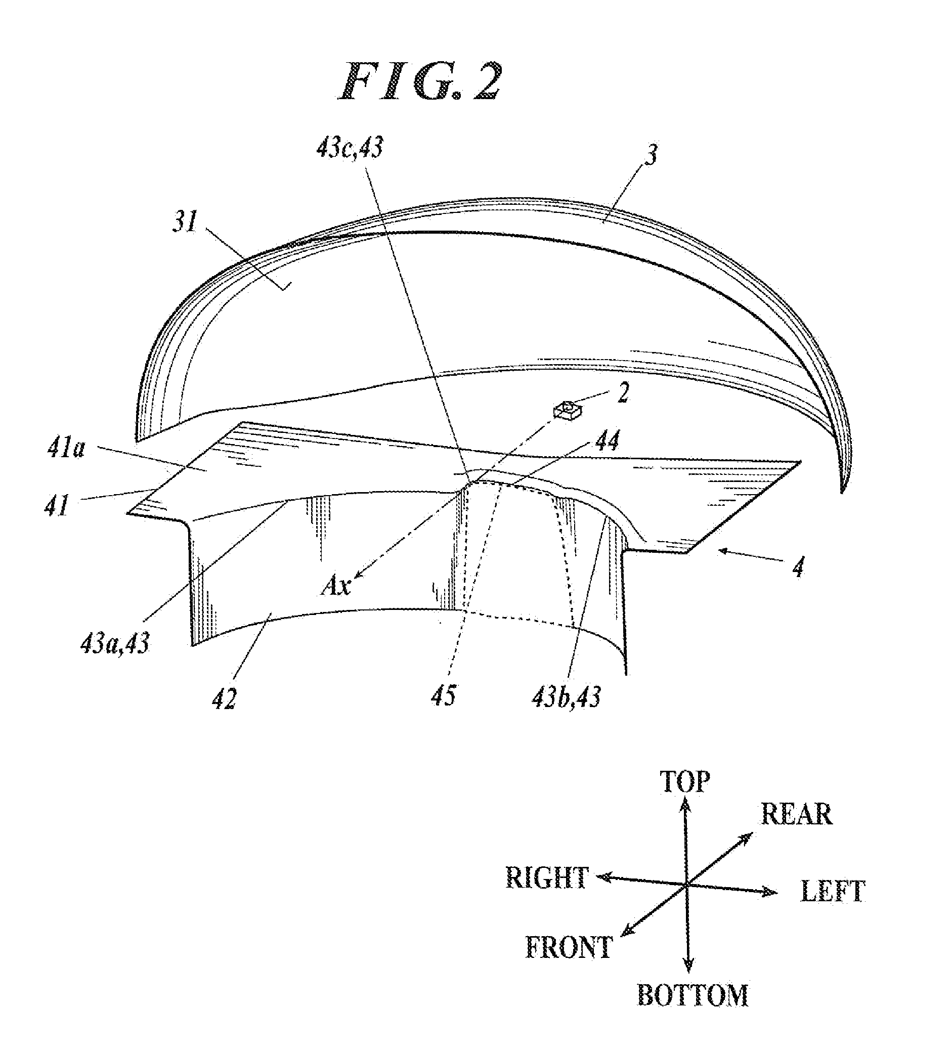
[0028]As illustrated in FIG. 1, the vehicle headlamp 1 is a projector-type headlamp, which is equipped with a vehicle (not illustrated) and generates a predetermined light distribution pattern (a low beam) in the front direction of the vehicle. The vehicle headlamp 1 includes a light source 2, a reflector 3, a shade 4 and a projection lens 5.

[0029]The light source 2 is a light emitting diode (LED) arranged such that an emission surface thereof faces upwards. Here, the light source 2 may be other type of light source su...


PUM


Abstract

A vehicle headlamp includes a light source, a reflector, a projection lens, and a shade. The shade has an upper end edge portion and a raised portion. The upper end edge portion has a projection. The reflector reflects light output from the light source in the front direction. The projection lens in front of the light source projects the light. The shade between the reflector and the projection shields a portion of the light. The upper end edge portion contributes to form the upper end line of the low beam as a cut-off line. The projection contributes to form a recession of the cut-off line recessed below a specific point in the low beam. The raised portion reflects the light having passed above the projection to illuminate an inner region of the recession.

Description

[0001]This application claims the priority benefit under 35 U.S.C. §119 of Japanese Patent Application No. 2011-186678 filed on Aug. 30, 2011, which is hereby incorporated in its entirety by reference.FIELD[0002]The presently disclosed subject matter relates to a vehicle lighting device.DESCRIPTION OF THE RELATED ART[0003]Heretofore, as a vehicle headlamp such as a headlight for an automobile, a so-called projector-type vehicle headlamp has been known, as illustrated in FIG. 7. In such a projector-type vehicle headlamp, the light output from a light source 61 is projected in the front direction of the vehicle through a projection lens 63 after having been reflected by a reflector 62. In the projector-type vehicle headlamp, a portion of the light to be incident on the projection lens 63 is shielded by a shade 64 provided between the reflector 62 and the projection lens 63. Thus, as illustrated in FIG. 8, a low beam LB is generated by the light illuminating only below a cut-off line C...

Claims


Application Information

Patent Timeline
IPC IPC(8): B60Q1/04
CPCF21S41/43
Inventor YAMAGATA, SHINJIAKUTAGAWA, TAKASHI
Owner STANLEY ELECTRIC CO LTD
Why Eureka
Try Eureka