Fuel feed unit

a technology of fuel feed and housing parts, which is applied in the direction of positive displacement liquid engines, piston pumps, lighting and heating apparatus, etc., can solve the problems of housing parts being sealed off with respect to the rotor, housing parts not being entirely made of plastic, etc., and achieves the effect of preventing heat input to the housing part which faces the electric motor, and reducing the risk of rotor sealing

Inactive Publication Date: 2010-05-04
VITESCO TECH GERMANY GMBH
View PDF28 Cites 2 Cited by
  • Summary
  • Abstract
  • Description
  • Claims
  • Application Information

AI Technical Summary

Benefits of technology

[0005]This embodiment allows the housing part to expand in the event of heat input or friction. The change in shape of the housing parts can be absorbed by means of corresponding arrangement of the expansion joint or of a plurality of expansion joints and can thus be kept away from the mounting of the shaft and from the rotor. The gap seal between the housing parts and the rotor can be kept largely constant by means of the invention even in the event of thermal expansion of the housing parts. As a result, the generation of further friction is kept particularly low, and the fuel pump is largely prevented from seizing. The fuel feed unit according to the invention can therefore be operated in a dry state and thus without fuel for a particularly long period of time without the fuel pump seizing.
[0014]The production costs of the fuel feed unit according to the invention can be further reduced if the axial section and the radial section are produced in one piece.

Problems solved by technology

In known fuel feed units for gasoline fuels, the housing parts, including the bearing for the shaft, could not be produced entirely from plastic since a change in shape as a result of swelling of the plastic on contact with fuel, in addition to that caused by the heat input from the electric motor, prevents the housing parts from being sealed off with respect to the rotor.

Method used


Image

  • Fuel feed unit
  • Fuel feed unit

Examples


Embodiment Construction

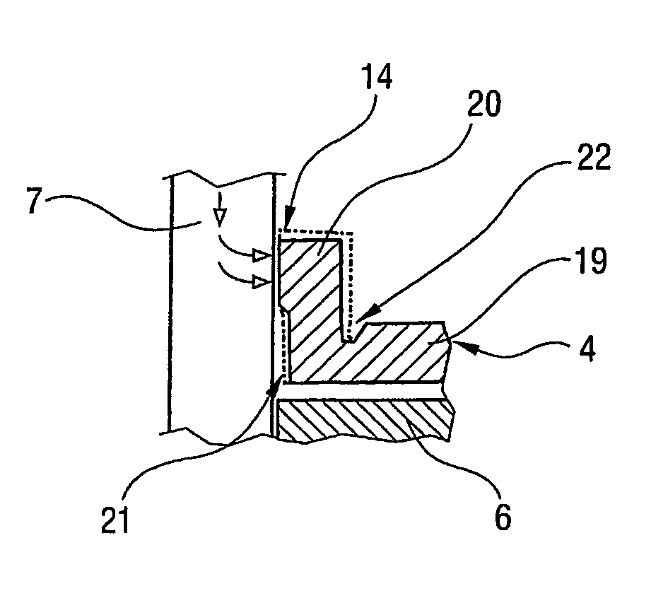
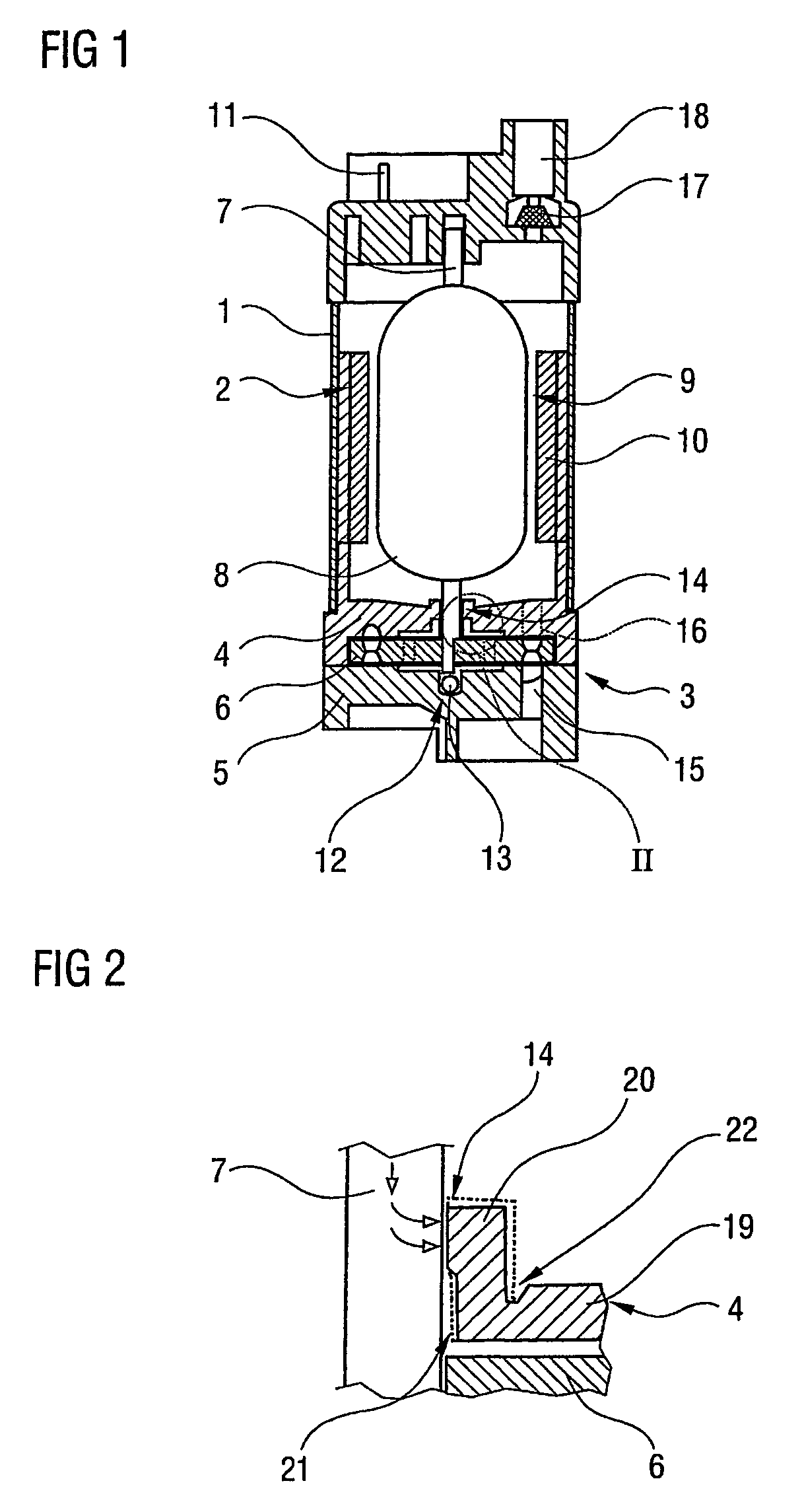
[0018]FIG. 1 shows a fuel feed unit, intended for arrangement in a fuel tank of a motor vehicle, having a housing 1 and having a fuel pump 3 driven by an electric motor 2. The fuel pump 3 is embodied as a side-channel pump and has a rotor 6 which is rotatably arranged between two housing parts 4, 5. The rotor 6 is fastened to a shaft 7 of the electric motor 2. The electric motor 2 has a rotor 9, which includes coils 8 and the shaft 7, and a stator 10, with magnetic shells, which is connected to the housing 1. The electric motor 2 can be supplied with electric current by means of electrical contacts 11 which are arranged on the outside of the housing 1. The feed unit has an axial bearing 12 with a ball 13, which is arranged in the housing part 5 facing away from the electric motor 2 and supports the shaft 7, and a radial bearing 14 in the housing part 4 which faces toward the electric motor 2.

[0019]When the rotor 6 is driven, the fuel pump 3 sucks in fuel via a suction duct 15 and fe...


PUM


Abstract

A fuel pump unit comprising a housing part (4) arranged between an electric motor (2) and a fuel pump (3). The housing part is provided with expansion joints for compensating thermal expansions or swelling of the material of the housing part (4). The gap between the impeller (6) and the housing parts (4, 5) of the fuel pump (3) can be kept constant by virture of the expansion joints, whereby the fuel pump (3) is essentially prevented from jamming especially when it runs dry.

Description

BACKGROUND OF THE INVENTION[0001]The invention relates to a fuel feed unit for a motor vehicle having a fuel pump which is driven by an electric motor, and having a rotor of the fuel pump arranged between two housing parts, the rotor being fastened in a rotationally fixed manner to a shaft of the electric motor.[0002]Fuel feed units of this type are frequently used in modern-day motor vehicles and are known from practice. The housing parts of the fuel pump are produced mainly from metal or a sintered ceramic, or have a sintered bush, which is pressed into plastic, as a bearing for the shaft. The housing parts are separated from the rotor by a particularly small clearance and thus form a gap seal of the fuel pump. Heat input as a result of friction or heat from the electric motor leads, however, to the housing parts and the rotor expanding, and thus to a reduction in the gap between the housing parts and the rotor. As a result, further friction occurs in the fuel pump which, in the w...

Claims


Application Information

Patent Timeline
Patent Type & Authority Patents(United States)
IPC IPC(8): F04B35/04F01D25/26F04D5/00F04D29/04F04D29/047F04D29/40
CPCF02M37/048F04D29/406F04D29/047F04D5/002F04D13/06F04D29/007F04D29/026F04D29/044F05D2210/11F05D2260/60F05D2300/43Y10S415/00
Inventor DEICHMANN, JOHANNESJAEGER, BERNDSCHMIDT, CHRISTOPH
Owner VITESCO TECH GERMANY GMBH
Why Eureka
Try Eureka