Apparatus for guiding a flexible member

a flexible member and apparatus technology, applied in the direction of printers, projectors, cameras, etc., can solve the problems of inability to use the winches of this type in applications, the total length of the line is greater, and the coils in the upper layer of the cable can become embedded into, etc., to achieve the effect of reducing tension, reducing load, and reducing tension

Inactive Publication Date: 2015-06-23
MATHCLICK
View PDF32 Cites 3 Cited by
  • Summary
  • Abstract
  • Description
  • Claims
  • Application Information

AI Technical Summary

Benefits of technology

[0016]The terms “pulley” and “drum” are used in the following description to denote generally cylindrical bodies for guiding a flexible member, the “pulley” typically having a shorter axial dimension than the “drum”. However, references to a “pulley” may alternatively be references to a further “drum”. Alternatively, the pulley and or the drum may be arranged as two or more co-rotating pulleys or short drums, connected for simultaneous rotation by one or more smaller diameter or enlarged diameter connecting portions. Reduced diameter connecting portions advantageously reduce the weight of the or each drum and the associated material cost.
[0046]The invention could further be used to provide a continuous cable drive mechanism, a compact transmission device in a marine wave energy conversion system or an offshore or deep well winch having a higher load rating for use with very long runs of flexible member. The invention can also be used in applications using endless drive belts, for example cam belts and / or fan belts in vehicles as it permits the use of a lower tension belt that is cheaper, simpler and more durable than standard belts or chains and generates less friction.

Problems solved by technology

However, winches of this known type cannot be used in applications in which the total length of the line is greater than that which can be accommodated by the drum.
A further problem of such known winches is that the coils in an upper layer of cable can become embedded into the gaps between the coils of a lower layer of cable.
This causes friction between the layers resulting in wear of the cable.
It also impedes smooth operation and limits the load rating of the winch.
This results in frictional wear of the cable, mechanical shock to the system and noise.
In deepwater winching applications (e.g. ocean bottom perforation or pipe laying applications) where the system is partially dry and partially wet due to components of the system being above and below the water line, variations in the co-efficient of friction of the cable relative to the drum make slippage even more undesirable.
Known winches are also not optimally designed for heavy load, deepwater applications such as marine deep water operations which can require very long runs of cable (e.g. 4000 metres) for which a drum hundreds of metres long would be required to receive the cable.
A known way to improve marine systems is to segment the cable and raise and lower it in sections but this method is complicated and unsuitable for high load applications.
However, this is a complicated device having a limited load rating and requiring a slidable spooling head to change the position of the flexible member on the drum.
It also requires superposition of coils of cable which are likely to interfere with one another and cause unwanted cable wear.
This is achieved by a complicated, delicate and inefficient mechanism that permits only limited rotation of the drum in either direction, making it unsuitable for applications involving a high load or long runs of cable.
The number of turns of the drum is determined by the length of the screw and is therefore very limited.
There are also significant stresses on the cable as it moves between threads on the screw.
However, because the cable grooves on the drum and capstan are offset by half the separation of the grooves, the cable is subject to unwanted stresses and friction of the cable as the drum and capstan rotate and the cable slips and jumps out of the grooves on the drum and into the grooves on the capstan and vice versa.
In a first embodiment the cable is allowed to slip on the surface of a deflecting pulley, resulting in significant wear of it.
The presence of the grooves, which change the angle of the cable as it passes from one wheel onto the other, inevitably leads to rubbing of the cable and associated wear.
Also in this second embodiment the assembly also might permit some movement of the cable across the surface of the drive wheels as they rotate resulting in cable wear.

Method used


Image

  • Apparatus for guiding a flexible member
  • Apparatus for guiding a flexible member
  • Apparatus for guiding a flexible member

Examples


first embodiment

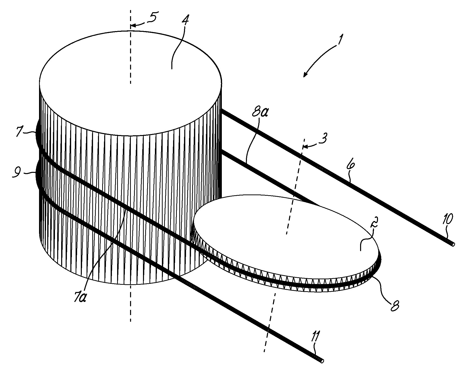
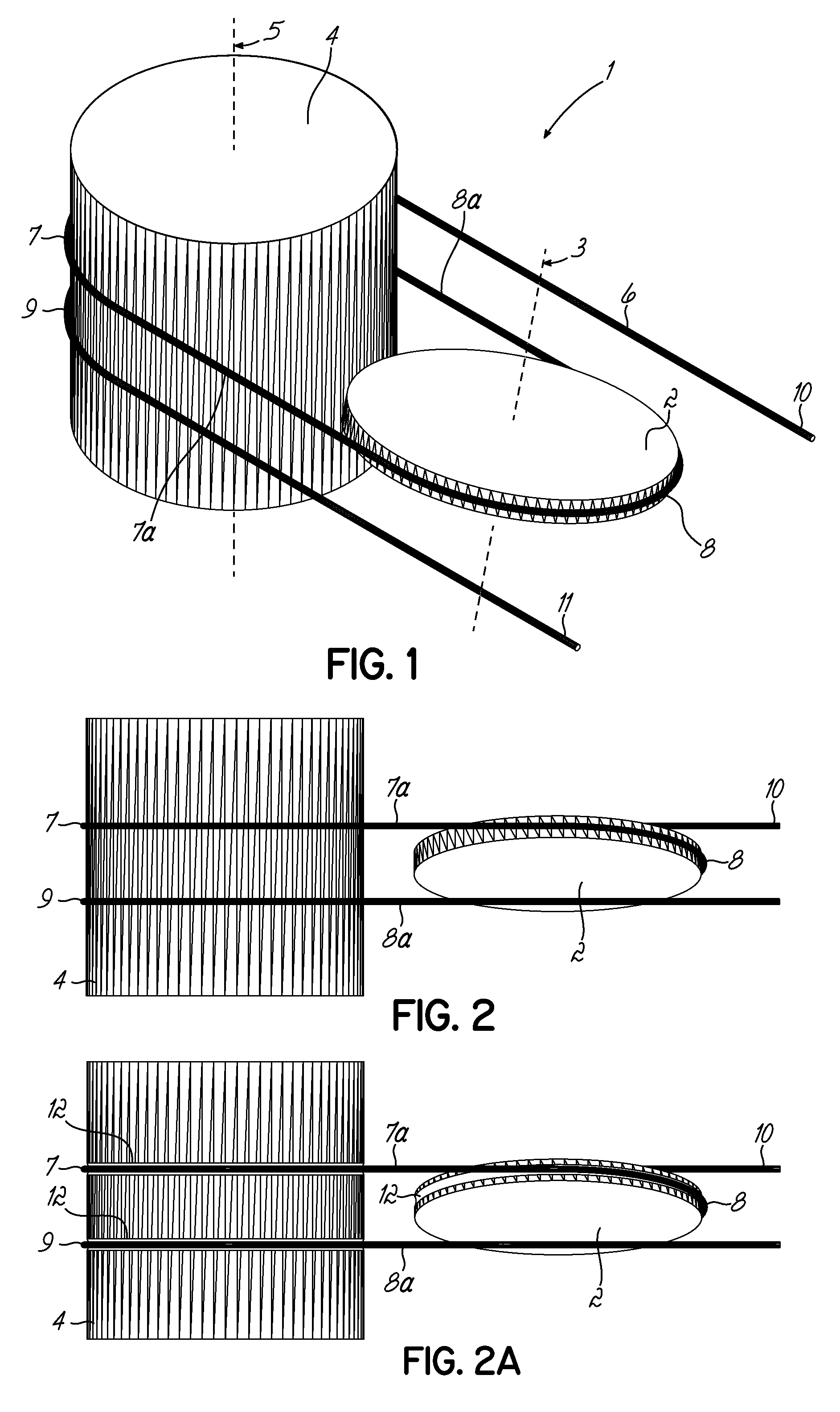
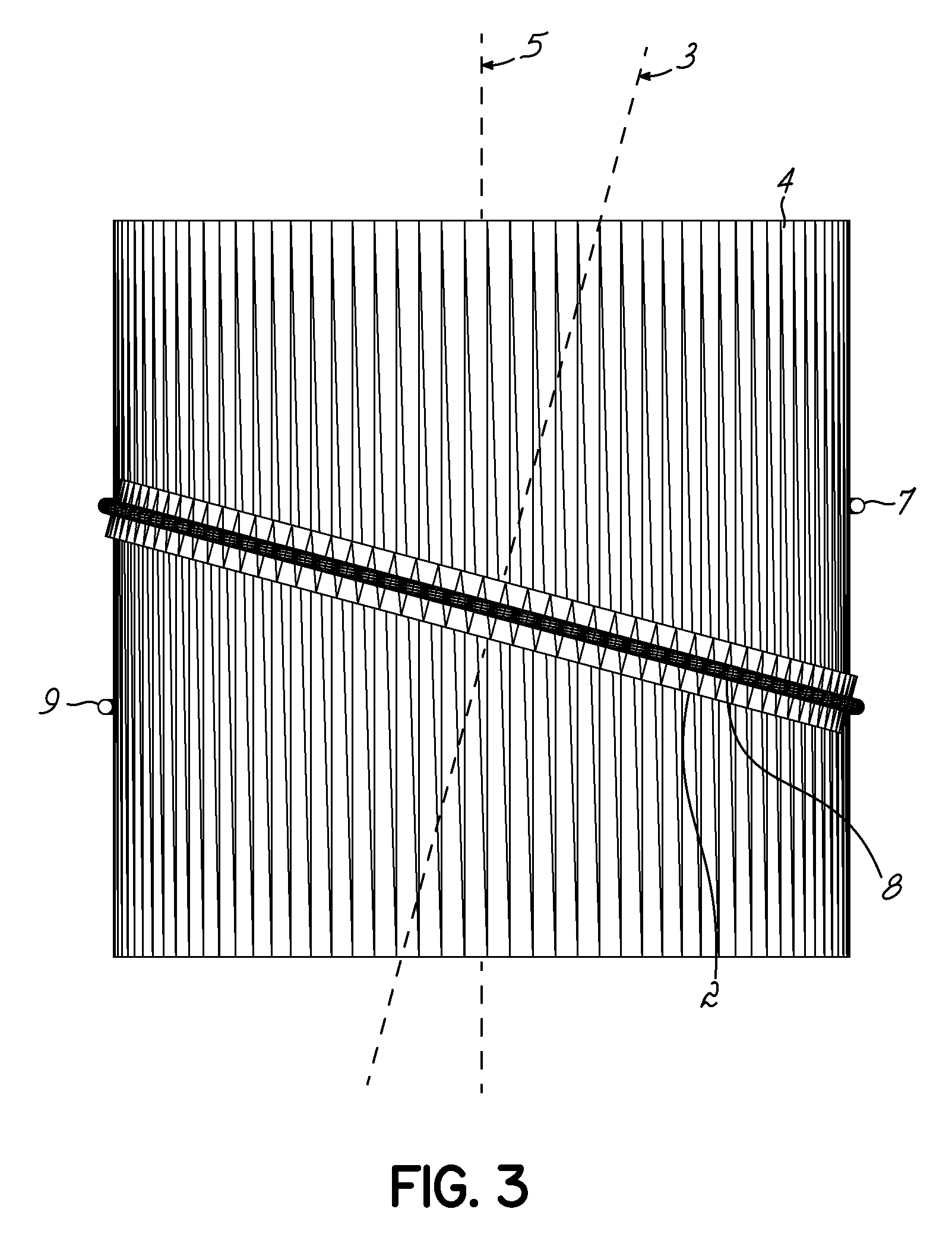
[0059]FIGS. 1 to 3 show an apparatus 1 for guiding a flexible member 6 onto a drum, the apparatus comprising a pulley 2 rotatable about a pulley axis of rotation 3 and a drum 4 rotatable about a drum axis of rotation 5. The pulley axis 3 is inclined at an acute angle relative to the drum axis 5.

[0060]The drum 4 is preferably an elongate cylindrical body. The drum may however be an alternative shape preferably having a curved outer surface. The drum may also be a component, for example an input or output shaft, of a mechanical drive apparatus. The pulley 2 is preferably a further cylindrical body having a shorter axial dimension than the drum. The pulley may however be an alternative shape such as a more elongate cylindrical body forming, for example another drum.

[0061]The pulley axis 3 is spaced from, and inclined to, the drum axis 5 in an arrangement in which the shortest imaginary line extending between the drum and pulley axes is perpendicular to the axes of both the drum and pu...

fourth embodiment

[0090]FIGS. 8 to 10 show an apparatus 301 according to the invention in which one or more additional pulleys may be associated with any drum, each additional pulley adding a further pair of drum portions of wrap on fixed axial diametrical positions on the drum. Each of the pulleys is inclined relative to the corresponding drum so that in use of the apparatus, the pair of drum portions of wrap associated with each pulley remain on different pairs of fixed, axially spaced diametrical planes of the drum and the pulley portion of wrap and the first and second connecting portions of the flexible member path associated with each pulley remain on a fixed diametrical plane of that pulley.

[0091]The pulleys may be arranged in a stacked configuration adjacent to one or more of the drums. The pulleys may be arranged so that the pairs of first and second drum portions of wrap associated with each pulley are adjacent one another on the drum surface or interposed between one another so as to contr...


PUM


Abstract

An apparatus (1) for guiding a flexible member (6) comprising a drum (4) mounted for rotation about a drum axis (5) and a pulley (2) mounted for rotation about a pulley axis (3), the drum and pulley axes being inclined. The apparatus defines a path for the flexible member including first and second drum wrap portions (7,9) on axially spaced first and second fixed drum diametric planes, a pulley wrap portion (8) on a fixed pulley diametric plane, and first and second connecting portions (7a, 7b). The arrangement is such that the connecting portions (7a, 7b) lie on the respective first and second drum diametric planes and both lie on the pulley diametric plane. As the drum (4) and pulley (2) rotate with the flexible member (6) in use, the arrangement is such that the first and second drum wrap portions (7,9) remain on the fixed drum diametric planes and the pulley portion of wrap (8) remains on the fixed diametrical plane of the pulley. The apparatus reduces slippage of the flexible member (6) and associated wear.

Description

FIELD OF THE INVENTION[0001]This invention relates to an apparatus for guiding a flexible member. This invention also relates to a winch comprising the apparatus.[0002]The apparatus of the invention may be used to guide one or more flexible members onto one or more drums and to maintain fixed positions of portions of wrap of the one or more flexible members on the surface of the one or more drums.BACKGROUND TO THE PRESENT INVENTION[0003]Winches, for example car or sailboat winches, are known in which a length of cable is attached at one end to a drum and an end of the cable can be unwound from and rewound onto the drum. Manual effort, or an automated cable feeding device, is typically required to guide the cable onto the drum. The cable is moved along the surface of the drum as it is wound in order to form adjacent coils on the surface of the drum and the cable is typically laid over itself in layers.[0004]As the drum rotates, the coils move in space as if they were moving along a s...

Claims


Application Information

Patent Timeline
Patent Type & Authority Patents(United States)
IPC IPC(8): F03B13/10F03B13/14F16H7/04B66D1/74B65H57/14H02P9/04F03B13/12B66D1/36
CPCB65H57/14B66D1/7405F16H7/04B66D1/36F03B13/14Y02E10/38Y02E10/30F16H7/02F16H55/36
Inventor GRASSI, MICHELE
Owner MATHCLICK
Why Eureka
Try Eureka